2.2.3.1 Interconnection Between PIC32CXMTC-DB and MCP3914-EB
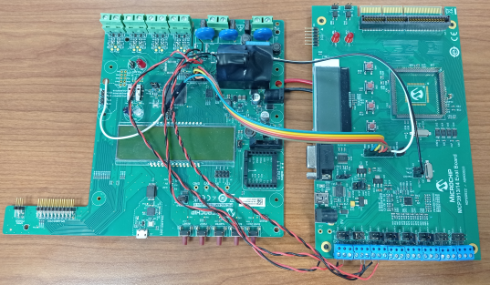
Connections between PIC32CXMTC and until 3 MCP3914 using SPI with different CS signals the same RESET signal for all the MCP3914. In this example, only CS0 signal is used.
| MCP3914 EB | PIC32CXMTC-DB | MCP3914 Board Number | ||
|---|---|---|---|---|
| J8 – 1 | RESET | TP68 | PD12 | 0,1,2,3 |
| J8 – 3 | MOSI | J14-10 | MCP3910_PD7 (MOSI) | 0,1,2,3 |
| J8 – 5 | MISO | J14-8 | MCP3910_PD6 (MISO) | 0,1,2,3 |
| J8 – 7 | SCK | J14-7 | MCP3910_PD5 (SPCK) | 0,1,2,3 (*) |
| J8 – 9 | CS0 | J14-9 | MCP3910_PD8 (NPCS) | 0 (**) |
| J8 – 9 | CS1 | EXT CONN | PD9 | 1 |
| J8 – 9 | CS2 | EXT CONN | PD10 | 2 |
| J8 – 9 | CS3 | EXT CONN | PD11 | 3 |
| J8 – 11 | DR | U7 – 25 | ITOUT (PD0) | |
| J3 – 5 | CLKI | U7 – 30 | MCLK (PD4) | |
| J10- | GND | J3- | GND | |
| J10+ | 9V | J3+ | 9V | |
Note:
- (*) A serial resistor may be required to maintain the signal integration. The evaluation board mounts R17 (10 Ohms), but it is placed before the connector J3.
- (**) In case of several MCP3914, only DR signal from the MCP3914 number 0 is connected to PIC32CXMTC.
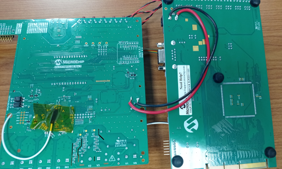
Modifications Required in MCP3914 Evaluation Board
- Remove module of the micro-controller.
- Jumper J6 connected (DR signal requires a 1k pull-up resistor).
- Jumper J9 selects power supply from 9V (by default, it is selected the USB position).
Modifications Required in PIC32CXMTC-DB
- J15 removed (PD5-8 goes to J14 instead of ATSENSE).
- U7 (ATSENSE) removed: ITOUT, MCLK are disconnected from ATSENSE. Alternatively, ITOUT and MCLK tracks could be cut.
- PD12 requires a pull-up resistor. For testing purposes, internal pull-up of the GPIO could be used.
- Remove D1 to avoid powering MCP3914 evaluation board with 12V (see below explanation).
Power Supply
MCP3914 board works at 9V and PIC32CXMTC-DB at 12V (although it is able to work at 9V).
If the PIC32CXMTC-DB is powered from mains or V1 input is connected, the TRACO power supply will fix 12V as power supply voltage in PIC32CXMTC-DB. As power supply line is the same for both boards, it could damage MCP3914 evaluation board, so, it is required remove D1 from PIC32CXMTC-DB in order to neutralize TRACO power supply and power both board with a 9V external power supply.
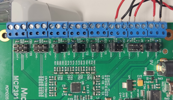
Additional Modifications to Connect the Metrology Inputs to the WECO Tester
- Channels CH0, CH1 and CH2 are configured to measure voltage in single-ended mode.
- Channels CH3, CH4 and CH5 are configured to measure current in differential mode.
- Voltage and current inputs include anti-aliasing filter with cut-off frequency of 16 kHz.
| METROLOGY INPUTS CONNECTION | |||
| Component | Old Value | New Value/Action | Notes |
| C1, C2, C8, C9, C47, C50 | 0.1u | 3.3 nF | CH0 (V1), CH1 (V2), CH2 (V3) |
| R4, R11, R19, R21, R18, R65 | 1k | Remove | CH0 (V1), CH1 (V2), CH2 (V3) |
| R3, R13, R15, R22, R16, R67 | 1k | 4.42k | CH0 (V1), CH1 (V2), CH2 (V3) |
| C51, C52, C53, C54, C55, C56 | 0.1u | 10 nF | CH3 (I1), CH4(I2), CH5 (I3) |
| R69, R71, R75, R77, R81, R83 | 1k | 1.62 | CH3 (I1), CH4(I2), CH5 (I3) |
| MTC Board | |||
| D1 | Included | Remove | Power supply 12V (TRACO) disabled |
| R31, R43, R55 | 4.42k | Remove | |
| FLYING WIRES BETWEEN BOARDS | |||
| TP25 (MTC) to CH0+ (MCP) | V1. Use a GND wire twisted with the signal wire. Connect the wire to J2 (MCP3914 board). | ||
| TP28 (MTC) to CH1+ (MCP) | V2. Use a GND wire twisted with the signal wire. Connect the wire to J5 (MCP3914 board). | ||
| TP31 (MTC) to CH2+ (MCP) | V3. Use a GND wire twisted with the signal wire. Connect the wire to J20 (MCP3914 board). | ||
| METROLOGY INPUTS CONNECTION | |||
| Voltages | Voltage sources connected from WECO tester to PIC32CXMTC board voltage inputs V1, V2, V3, VN (J1, J2 connectors). | ||
| Currents | Current sources connected from CT outputs to MCP3914 board channels CH3 (I1, J22 connector), CH4(I2, J24 connector), CH5 (I3, J26 connector). | ||
- The jumpers of the input
networks (J1, J4, J7) for the voltage measurement only must connect the CHx-
to GNDA, the rest of the jumpers in the connector must be unconnected.Warning: The schematic of the board has an errata regarding the channel number in the external connector).
- The jumpers of the input networks (J21, J23, J25) for the current measurement only must connect the 3-4 pins, 1-2 and 5-6 pins (CHx+ and CHx-) must be unconnected.