1.2.5.5 Metrology Driver Configurations
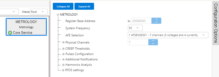
Metrology Driver is configured through its MCC component.
Metrology Driver in Demo Meter examples comes configured to demonstrate different functionalities.
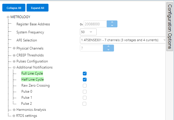
By default, 50Hz Mains frequency is selected.
- ATSENSE203 in PIC32CXMTSH-DB
- ATSENSE301 in PIC32CXMTC-DB (as seen in the figure above)
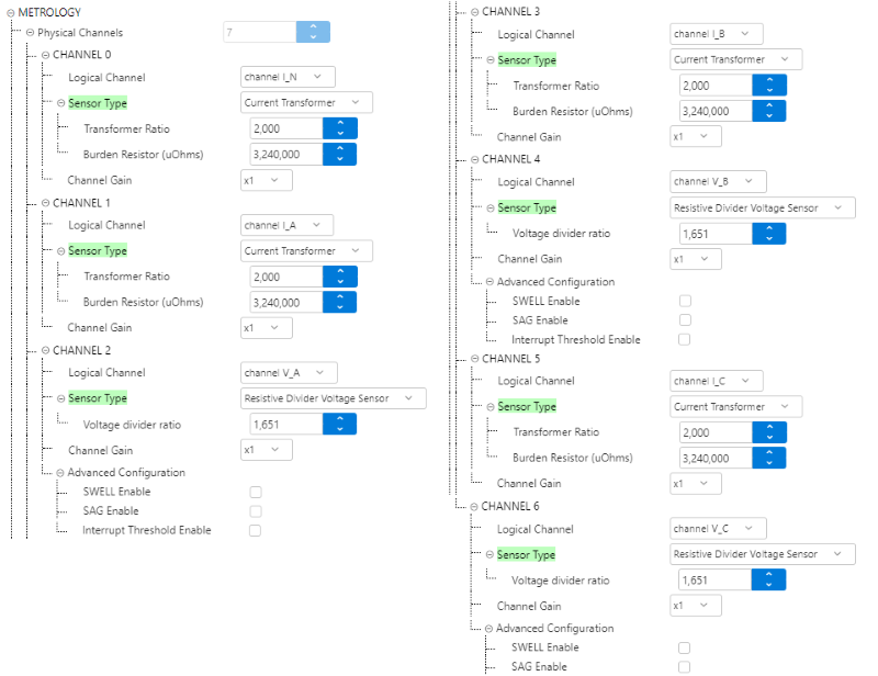
The Phisical Channels are set to match the connections between AFE and physical lines in the Development Boards.
For PIC32CXMTC-DB the configuration is the following:
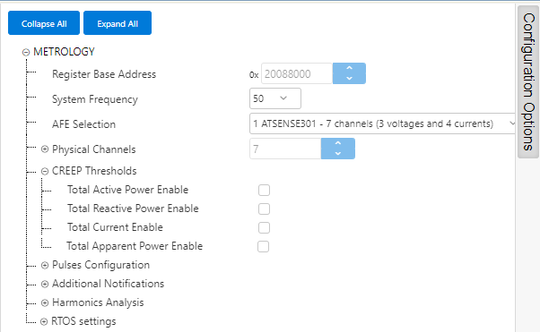
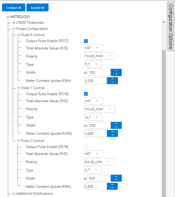
Creep Thresholds are disabled by default.
- Pulse 0 is configured to output Net Active Energy, with High polarity, pulse width of 464, and a Meter Constant providing a rate of 3200 pulses/kWh
- Pulse 1 is configured to output Net Reactive Energy, with High polarity, pulse width of 464, and a Meter Constant providing a rate of 3200 pulses/kWh
- Pulse 2 is disabled
Full Line Cycle and Half Line Cycle notifications are enabled in the provided examples, as they are used to retrieve per-cycle measurements and to indicate Events by the example application.
Other Notifications are not enabled.
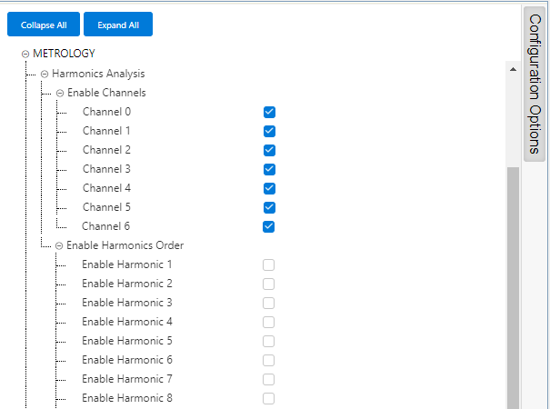
The Harmonics Analysis is enabled for all channels, but no harmonic is selected by default. This means that the harmonics are not calculated at start-up, and the user will trigger this analysis on demand using the Console Commands available.
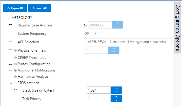
RTOS Settings define the Priority and Stack Size for the Metrology Driver Task.