4.2.1 Configuration of SAFLOCK Feature
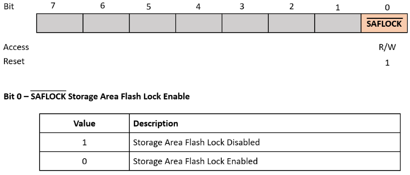
To enable the SAFLOCK feature, program the SAFLOCK bit of the
CONFIG13 Configuration register to 0.

The SAF area spans the end of the program memory, and the code stored in the SAF area cannot be executed by the CPU. Also, the expansion of the SAF region progresses upwards within the SAF Block and extends toward the Application Block, by increasing the SAF area through the SAFSZ Configuration bits.
Once the SAFLOCK feature is enabled, the configured SAF area will be permanently locked.
It is important to note that once the SAFLOCK feature has been enabled, SAFSZ can still
be increased, but it can never be decreased. Once the SAFLOCK
configuration bit has been activated, it is permissible to expand the region by writing
a value of 0 to the individual bits of SAFSZ. However, it is not
possible to reduce the size of the SAF, as erasing or writing a value of
1 to SAFSZ is prohibited. Therefore, it is important to configure
the desired SAF area and write the content to the SAF area before enabling the SAFLOCK
feature.
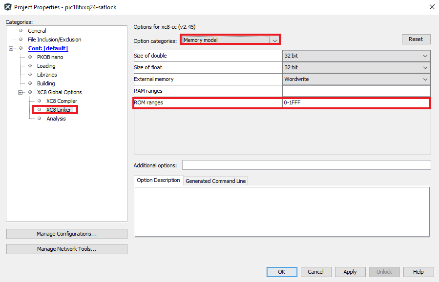
In the firmware project, it is necessary to configure the application code block to the specified program size to ensure that the application code does not overlap with the configured SAF area.

