
1.2.5 PIC32MZ Embedded Graphics With Stacked DRAM (DA) Starter Kit (Crypto): Building and Running the USB Host MSD Bootloader Applications
Downloading and Building the Application
To clone or download this application from Github, go to the main page of this repository and then click Clone button to clone this repo or download as zip file. This content can be download using content manager by following these instructions.
Path of the application within the repository is apps/usb_host_msd_bootloader/.
To build the application, refer to the following table and open the project using its IDE.
Bootloader Application
| Project Name | Description |
|---|---|
| bootloader/firmware/pic32mz_das_sk.X | MPLAB X Project for PIC32MZ Embedded Graphics With Stacked DRAM (DA) Starter Kit (Crypto) |
Test Application
| Project Name | Description |
|---|---|
| test_app/firmware/pic32mz_das_sk.X | MPLAB X Project for PIC32MZ Embedded Graphics With Stacked DRAM (DA) Starter Kit (Crypto) |
Setting Up PIC32MZ Embedded Graphics With Stacked DRAM (DA) Starter Kit (Crypto)
- Connect a micro USB cable to the UART-USB port J5
- For programming, connect a micro USB cable to the USB Debug port J19Note: Do not connect the micro USB cable to a USB Hub.
- Use the USB Host Type A Connector J7 to connect USB Flash Drive to the starter kit
Running the Application
- Open the test application project test_app/firmware/pic32mz_das_sk.X in the IDE.
- Build the project to generate the binary (Do not program the binary).
- Open the bootloader project bootloader/firmware/pic32mz_das_sk.X in the IDE.
- Build and program the application using the IDE.
- LED1 will be turned-on once programming is completed and bootloader starts running.
- Open the Terminal application (e.g., Tera Term) on the computer to get test application messages through UART once bootloaded.
- Configure the serial port settings as follows:
- Baud: 115200
- Data: 8 Bits
- Parity: None
- Stop: 1 Bit
- Flow Control: None
- Copy the generated application binary file to a USB Flash drive from the Host
PC.
-
- <harmony3_path>\bootloader_apps_usb\apps\usb_host_msd_bootloader\test_app\firmware\pic32mz_das_sk.X\dist\pic32mz_das_sk\production\pic32mz_das_sk.X.production.bin
-
- Rename the copied application binary file to image.bin.
- Insert the USB Flash Drive with the application binary image.bin to the Host connector on the device.
- Once the application is successfully programmed LED3 should start blinking and
the user should see below output on the console.
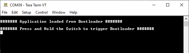
- Remove the USB Flash Drive from the Host connector.
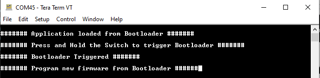
- Press and hold the Switch SW1 to trigger Bootloader from test application and
the user should see below output.
- Repeat Steps 10-12 once and jump to Step 15.
- This step is to verify that bootloader is running after triggering bootloader from test application in Step 13
- Press and hold the Switch SW1 and then Power cycle the device to force trigger bootloader at startup.
- Repeat Steps 10-12 once.
- This step is to verify whether bootloader is triggered by switch press at reset
Additional Steps (Optional)
- To bootload any other application, refer to the Application Configurations
- Once done, repeat the applicable steps mentioned in Running the Application