
1.1 Basic Working Principle
First, the operation of the TON generator block will be examined. This block comprises of a comparator with its inverting terminal biased at a fixed threshold (VTH) and its noninverting terminal connected to the positive side of the CTON capacitor. A constant current source (IT) charges the capacitor. When the voltage across the capacitor surpasses VTH, the output of the TON generator switches to a high state; conversely, when the voltage falls below VTH, the output switches to a low state. Refer to Figure 1-2 for the overall operation of the COT control method.
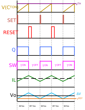
ON Time: The ON time begins when the high-side FET (HS) turns on. This occurs when the output voltage (or any derivatives of it) falls to the level of VREF of the regulation comparator. Q = 1, hence Q = 0 when the high-side FET is on, which makes QN off and allows CTON to get charged by IT until it reaches the VTH threshold level. Consequently, the TON generator's output remains low, maintaining the SR latch in a high-state where Q = 1 and HS is turned on (with Q = 0, indicating the low-side FET (LS) is off). The on-state of HS increases the inductor current (IL) and output voltage (VOUT), persisting until the fixed on-time expires.
OFF Time: The OFF time begins when the fixed on-time expires. Once CTON charges to VTH, the TON generator's output becomes high, triggering a reset signal to the SR latch. This transition sets Q = 0 and Q = 1. Consequently, HS is turned off and LS is turned on, causing the inductor current and output voltage to ramp down. Additionally, with Q = 1, the CTON discharge FET (QN) is activated, discharging CTON to prepare it for the next charging cycle. The OFF time continues until the output voltage (or any derivatives of it) drops to the level of VREF (the threshold set at the noninverting terminal of the regulation comparator).
The minimum TOFF block is introduced to ensure that the bootstrap capacitor (not shown in the block diagram) has sufficient time to charge, especially during scenarios involving very high duty cycle operation. Bootstrap capacitors are crucial for the proper turn-on of the high-side FET and are charged (mostly from VDD or an auxiliary regulated power rail of the converter IC) only during the low-side FET's on-time (TOFF).
Maintaining a significant ripple (typically between 20 - 200 mV) at the feedback is crucial for the effective operation of COT control. However, relying solely on output capacitor ripple proves impractical in many cases. Hence, a key objective of this application note is to thoroughly explore various techniques for introducing ripple into the feedback loop.
While COT control boasts simplicity, robustness, and fast response, frequency variation can be substantial in response to changes in input voltage and, to a lesser degree, load.
Furthermore, COT may exhibit relatively poor line regulation because it senses the valley of the ripple for regulation purposes and the amplitude of the ripple is highly dependent on the input voltage. These two drawbacks are highlighted in Figure 1-3.
This is where Microchip's Adaptive Constant-On-Time (ACOT) control emerges as a solution, effectively mitigating the challenges associated with frequency deviations and inadequate voltage regulation encountered with the conventional COT control method.