
3.5.3 Smart Appliance Control on PIC32CM JH VL Curiosity Nano + Touch Evaluation Kit
Description
- Temperature Control mode
- BLE Control mode
-
Temperature Control mode: Automatically controls the DC fan based on the temperature measurement from Weather Click. Both the temperature value and fan speed are displayed on e-paper display. The temperature ranges corresponding to each fan speed are shown below.
- Temperature between 18 (64 F) to 25 (77 F) degree Celsius, the fan rotates at LOW speed.
- Temperature between 26 (78 F) to 30 (86 F) degree Celsius, the fan rotates at MEDIUM speed.
- Temperature is greater than 30 degree Celsius (86 F), the fan rotates at HIGH speed.
- Temperature is less than 18 (64 F), the fan is switched OFF.
-
BLE Control mode: Control the DC fan based on BLE commands from Microchip Bluetooth Data (MBD) app in smartphone. Besides, the user will be able to switch back to Temperature Control mode. The available commands for use are:
- FAN_ON: Turns
ONthe fan at LOW speed. - FAN_OFF:
Turns
OFFthe fan. - FAN_LOW: Runs the fan at LOW speed.
- FAN_MID: Runs the fan at MEDIUM speed.
- FAN_HIGH: Runs the fan at HIGH speed.
- TEMP_MODE: Switches to Temperature Control mode.
- FAN_ON: Turns
Modules/Technology Used
-
Peripheral Modules
- SYSTICK
- SERCOM (I2C)
- SERCOM (USART)
- SERCOM (SPI)
- PTC
- RTC
- Wireless RNBD Driver
- STDIO Library
- Touch Library
The following figure provides the MCC Harmony project graph with all the components.
Hardware Used
- PIC32CM JH-Value Line Curiosity Nano + Touch Evaluation Kit
- Curiosity Nano Base for click boards
- Fan Click
- WEATHER CLICK
- RNBD451 Add On Board
- MIKROBUS XPLAINED PRO
- MikroElektronika Eink Click Without Display
- MikroElektronika E-Paper display 2,9" 296x128 dots display
- 5V DC Fan
- Lipo Rechargeable Battery
Software/Tools Used
This project has been verified to work with the following versions of software tools:
Refer to the Project Manifest present in
harmony-manifest-success.yml under the project folder
pic32cm_jh_vl_cnano_smart_appliance_control/firmware/src/config/default/
.
Refer to the Release Notes to know the MPLAB X IDE and MCC Plug-in version.
- Install Microchip Bluetooth Data Android App in the Android mobile or
- Install Microchip Bluetooth Data iOS App in the iOS mobile
Due to Microchip regularly updates tools, occasionally issue(s) could be discovered while using the newer versions of the tools. If the project does not seem to work and version incompatibility is suspected, it is recommended to double-check and use the same versions that the project was tested with. To download original version of MPLAB Harmony v3 packages, refer to the document How to Use the MPLAB Harmony v3 Project Manifest Feature (DS90003305).
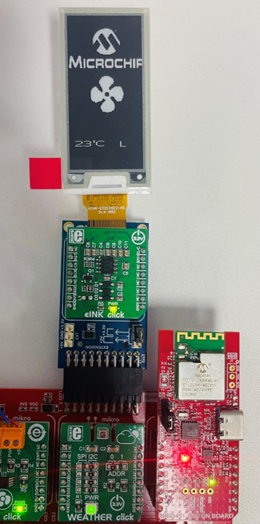
Hardware Setup
- Mount PIC32CM JH-Value Line Curiosity Nano + Touch evaluation kit on CNANO56_HOST_CONN (U3) connector of Curiosity Nano Base board.
- First connect the 4 wires from the Fan Click to the Fan (Red wire to +5V, Black wire to GND, Blue wire to PWM and Yellow wire to TACH of the Fan Click) and then mount the Fan Click board onto mikroBUS socket 1 connector of Curiosity Nano Base. The fan click uses the SERCOM2 I2C interface.
- Mount the Weather Click board onto mikroBUS socket 2 connector of Curiosity Nano Base. This Weather Click uses the SERCOM2 I2C interface.
- Connect the RNBD451 Add On
Board to the mikroBUS socket 3 connector of Curiosity Nano Base. The RNBD
module uses the SERCOM3 USART interface.
- Adjust the PWR SEL
(Power Supply Selection) Jumper JP1 to the mikro 3V3 setting (i.e,
short J1 and J2), designated for the mikroBUS interface on the
RNBD451 Add-On Board as indicated in the below image. By doing so,
this configuration enables the RNBD module to draw power directly
from the MCU's power supply. This eliminates the necessity of using
an additional USB cable to power up the RNBD451 Add-On Board.
- Connect the mikroBUS Xplained Pro to EXT 1 connector of Curiosity Nano Base board and mount the eINK Click and e-paper display onto the mikroBUS Xplained Pro. The e-paper display uses the SERCOM0 SPI interface.
- Connect the Lipo Battery to J1 connector of PIC32CM JH-Value Line Curiosity Nano + Touch evaluation kit and make sure battery switch is toggled to Battery ON position.
- Connect the PIC32CM JH-Value
Line Curiosity Nano + Touch evaluation kit to the host PC as a USB device,
through a Type-C USB (Debug USB) port.

Programming Hex File
The pre-built hex file can be programmed by following the below steps.
- Open MPLAB X IDE
- Close all existing projects in IDE, if any project is opened
- Go to
File>Import>Hex/ELF File - In the Import Image File
window,
- Create Prebuilt
Project,
- Click the Browse button to select the prebuilt hex file
- Select Device as PIC32CM6408JH00064
- Ensure the proper tool is selected under Hardware Tool and click the Next button
- Select Project
Name and Folder,
- Select appropriate project name and folder and click the Finish button
- Create Prebuilt
Project,
- In MPLAB X IDE, click the Make and Program Device button to program the device
- Follow the steps in Running the Demo section
Programming/Debugging Application Project
- Open the project
pic32cm_jh_vl_cnano_smart_appliance_control/firmware/pic32cm_jh_vl_cnano.Xin MPLAB X IDE - Ensure PIC32CM JH-Value Line Curiosity Nano + Touch evaluation kit is selected as hardware tool to program/debug the application
- Build the code and program the device by clicking on the Make and Program button in MPLAB X IDE tool bar
- Follow the steps in Running the Demo section
Running the Demo
Temperature Control Mode
- The demo initializes working in Temperature Control mode. Based on the temperature measurement from Weather click, the fan speed will be controlled automatically. The LED1 on the Curiosity Nano is turned ON to indicate that the application is in Temperature Control mode.
- The temperature reading in
degree Celsius, and the fan speed will be displayed on the e-paper display.
The fan speed will be indicated as follows:
- Fan Low speed –
L - Fan High speed –
H - Fan Medium speed –
M - Fan Off –
OFF
- Fan Low speed –
- To switch to BLE Control mode, press the touch button once. LED1 turns OFF indicating that the application has switched to BLE Control mode.
- Once the device switches to BLE Control mode, the user can control the fan by following the steps mentioned below.
BLE Control Mode
- Enable Bluetooth and Location from Smartphone settings
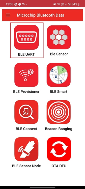
- Open the Microchip
Bluetooth Data (MBD) application on the smartphone and tap on the
BLE UART icon on the dashboard. If prompted, allow the
application to turn on Bluetooth.
- Scan for Bluetooth devices by
tapping
PIC32CXBZ>SCAN>SCANoptions on the MBD app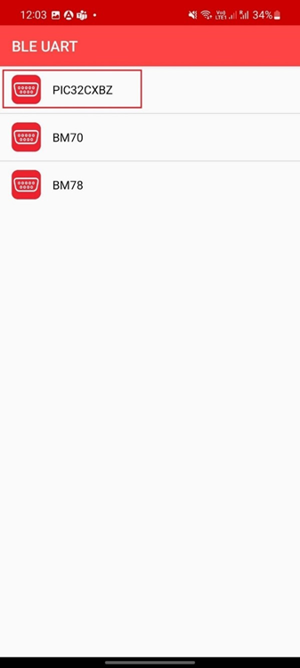
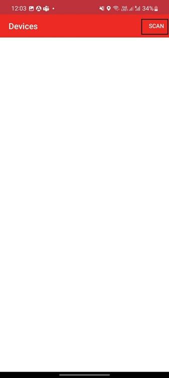
- The RNBD device should appear
as
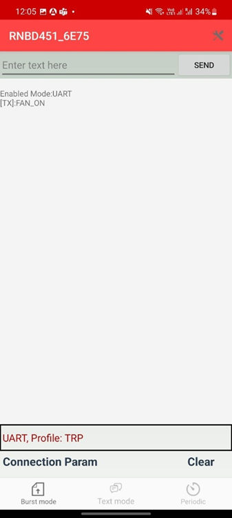
RNBD451_XXXX(or the device name configured in the RNBD firmware) in the list of Bluetooth devices - When
RNBD451_XXXXdevice appears, click the CANCEL button to cancel the device scanning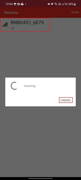
- Tap on the
RNBD451_XXXXdevice to connect to the device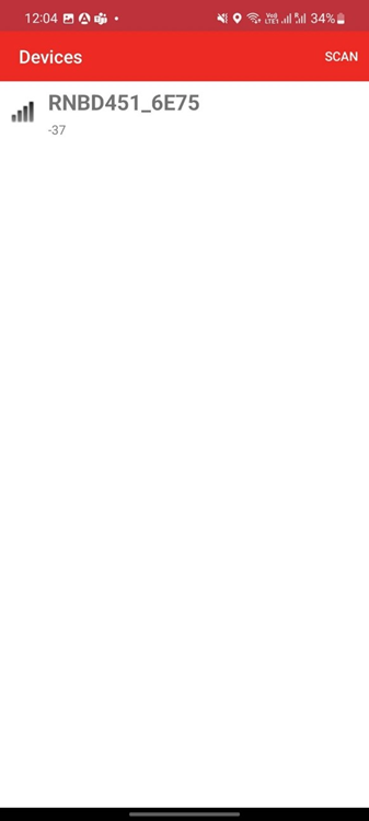
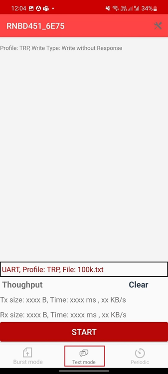
- Once the device is connected,
tap on the Text mode to transfer data to device to build the communication
interface between demo application and MBD app
- Send the command FAN_ON and
click the Send button to turn on the fan
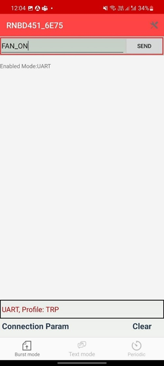
- User can provide the available BLE commands for this application to control the fan as desired
- In order to return to
Temperature Control mode again, user can either press the touch
button again or send the BLE command
TEMP_MODE. LED1 turns on again, indicating that the application has switched to Temperature Control mode.
Comments
- This application demo
builds and works out of box by following the instructions in Running
the Demo section. If the user needs to enhance/customize this
application demo, should use the MPLAB Harmony v3 Software framework.
Refer to the following links to setup and build the applications using
MPLAB Harmony.
- How to Setup MPLAB Harmony v3 Software Development Framework (DS90003232)
- How to Build an Application by Adding a New PLIB, Driver, or Middleware to an Existing MPLAB Harmony v3 Project (DS90003253)
- Video - How to Set up the Tools Required to Get Started with MPLAB® Harmony v3 and MCC
- Create a new MPLAB Harmony v3 project using MCC
- Update and Configure an Existing MHC-based MPLAB Harmony v3 Project to MCC-based Project