
1.1.6.1 I2S Peripheral Library Help
This section provides an interface to use the I2S peripheral.
Introduction
This library provides a brief overview of the I2S peripheral.
Description
The I2S module implements an I2S (Inter-IC Sound) interface, for connection between an MCU and an audio peripheral such as a codec or Bluetooth module.
The I2S module provides support to the audio protocol functionality via four standard I/O pins. The four pins that make up the audio protocol interface modes are:
SDI: Serial Data Input for receiving sample digital audio data (ADCDAT as output from the codec)
SDO: Serial Data Output for transmitting digital audio data (DACDAT as input to the codec)
SCKn: Serial Clock, also known as bit clock (BCLK)
FSn: Frame Select, also known as Word Select or Left/Right Channel Clock (LRCK)
In addition, there is a fifth line, called MCKn (Host Clock), which can be used to drive the codec.
There are two clock units in the I2S module, so n=1 or 2 depending on which is used. However there are only two data lines (SDO/SDI), one for each serializer (transmit/receive).
The SCK provides the clock required to drive the data out or into the module, while FS provides the synchronization of the frame based on the protocol mode selected. In I2S mode, the leading edge of audio data is driven out one SCK period of starting the frame.
In Host mode, the module generates both the SCK and FS.
In Client mode, the peripheral generates the BCLK and LRCLK signals, driving the SCK and FS pins of the I2S module. When in Client mode, the I2S cannot generate a Host clock (MCK), so a generic clock (GCLKn) must be used.
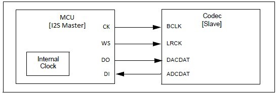
Host Mode
Host Generating its Own Clock – Output BCLK and LRCK
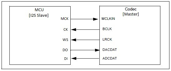
Client Mode
Codec Device as Host Derives MCLK from MCU Reference Clock Out
Using the Library
Configuring the Library
This section describes how to configure the peripheral library using the MHC.
Description
The library is configured for the supported processor when the processor is chosen in MPLAB X IDE, using the Microchip Harmony Configurator (MHC).
Choose the I2S peripheral by clicking on the appropriate instance under Peripherals->I2S in the Available Components section of MHC. (The I2S component may also be added automatically as a result of using a BSP Template, such as one for a codec or Bluetooth module).
When the I2S peripheral is clicked on in the Project Graph, the following menu is displayed in the Configurations Options:
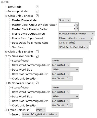
Typical values are shown for working in Client mode, with a codec such as the WM8904 in Host mode. DMA and Interrupt Mode are always enabled.
For each of the two Clock Units (0 and 1, only the first is shown):
Clock Unit n Enable -- if checked, the clock unit is enabled
Host/Client Mode can be either Host -- the I2S peripheral supplies the I2S clocks, or Client -- the peripheral such as a codec or Bluetooth module supplies the I2S clocks.
Using the Library
Host Clock Output Divisor -- the Generic I2S Clock (GCLK_I2S_n) is divided by this number to generate the Host Clock (MCKn)
Host Clock Division Factor -- the Host Clock (MCKn) is divided by this number to generate a serial clock SCKn
Frame Sync Output Invert -- the FSn signal is output with or without inversion
Frame Sync Input Invert -- the FSn signal is used with or without inversion on input
Data Delay from Frame Sync -- either 1 bit for I2S format, or 0 for left/right adjusted format
Slot Size selects the number of bits per slot: 8, 16, 24 or 32
For each of the Serializers (TX/RX):
Stereo/Mono selects stereo or mono (left channel is duplicated to the right)
Data Word Formatting Adjust selects left or right adjustment of data samples within the word
Data Word Size selects the number of bits per sample: 8, 16, 18, 20, 24 or 32 (or 8-bit compact stereo or 16-bit compact stereo)
Data Slot Formatting Adjust selects left or right adjustment of data samples within the slot
Clock Unit Selection selects which clock unit to use for this serializer, 0 or 1
Frame Select Pin specifies which pin is used as the FSn output as selected in the Pin Diagram
Invert selects whether the output of the I2S_LRCLK_Get function returns the true value or inverted one.
Using the Library
This topic describes the basic architecture of the I2S Peripheral Library and provides information and examples on how to use it.
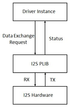
Abstraction Model
The I2S module sits between the I2S Driver, and the actual hardware.
Interface Header File: plib_i2sc.h
The interface to the I2S Peripheral Library is defined in the plib_i2sc.h header file. Any C language source (.c) file that uses the I2S Peripheral Library should include plib_i2sc.h.
Library Source Files:
The I2S Peripheral Library library source files are provided in the audio/peripheral/i2s_xxxx/src or audio/peripheral/i2s_xxxx/templates directory. This folder may contain optional files and alternate implementations. Please refer to Configuring the Library for instructions on how to select optional features.
Usage Model
The only usage model for the I2S Peripheral Library is to use a Interrupt/DMA model. Therefore the remaining functions normally associated with a PLIB like this (handling write or read requests, or returning transfer status), will be accomplished by the I2S driver directly communicating with the appropriate DMA functions, which is why they are not provided here.
The one function provided besides initialization is one for synchronizing with the left/right clock (LRCLK) for the I2S stream.
Example Applications:
This library is used by the following applications, among others:
audio/apps/audio_tone
audio/apps/audio_tone_linkeddma
audio/apps/microphone_loopback
Library Interface
This section describes the Application Programming Interface (API) functions of the Peripheral Library.
Refer to each section for a detailed description.
Initialization Function
Transaction Function