
2.2 Physical Realization
Adjusting the phase displacement, in turn, adjusts active power transferred across two AC sources connected through a reactive element, an inductor. When replacing the sinusoidal steady state voltage waveforms with “clipped” versions of 50% duty cycle rectangular waves with the same period (usually PWM peripheral), the operating principle remains valid. The dual active bridge, as the name suggests, is implemented with two full bridges. The DAB employs duality by gyration of the input voltage in the output current when averaged out across one operation cycle.
The class of converters which use two full bridges connected by a reactive element can satisfy the gyrator equations under certain modulation conditions. Out of all possible ways to control the bridges, there is a subset of combinations which satisfy the Gyrator mode of operation, meaning the transfer of input power proportional to input voltage into output power proportional to an output current. This gyrator-like operation differentiates the dual active bridge from other topologies.
Because the output of the converter is a natural current source, it’s possible that it can work seamlessly in Buck or Boost mode while maintaining a POPI (Power Out ~= Power In) condition beyond the constraints of the transformer ratio. The transformer component is optional and only benefits galvanic isolation. The transformer ratio can become important for power loss optimization but does not change the operating principle as a gyrator.
Because the output works as a natural current source, multiple DAB stages can be tied in parallel for current and power scaling purposes. DAB converters are well suited for battery charging applications, where the voltage across discharged and fully-charged batteries has a large difference, even for a greatly varied number of cells.
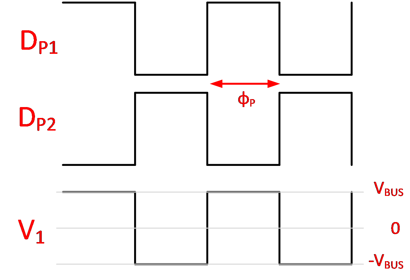
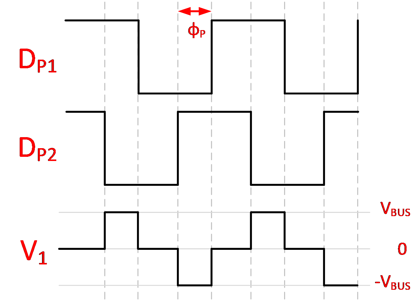
Regarding the PWM drive signals: all four half bridges, DP1 and DP2 on primary and DS1 and DS2 on secondary, are driven with complementary drive signals with a small dead-time when both are off. All drive signals always have 50% duty cycle and an equal period. Only the phase relative to each other will be adjustable and optionally, the period of all drive signals can be adjusted simultaneously.
Let’s denote the following terms:
- φP: phase shift between DP1 and DP2
- φS: phase shift between DS1 and DS2
- : Phase shift between V1 and V2
V1 is determined by the value of VBUS and by φP. If φP = 0°, then V1 = 0V (min value). If φP = 180°, then V1 is a square wave that alternates between -VBUS and +VBUS (max RMS value). Values of φP between 0° and 180° will cause the RMS value of V1 to vary between 0V and this full square wave. This is illustrated in Table 2-1.
|
|
The same holds true for V2, φS and VOUT.
With this in mind, and referring to Equation 2-4 and Figure 2-2, the power magnitude and direction can be modulated by changing φP, φS, the switching frequency FSW ( and θ (the phase shift between V1 and V2). These are the “knobs” used to control the power.
Phase-shift modulation (that is, controlling the power transfer via θ only) is the simplest and most common technique for DAB converters. With all other “knobs” fixed, by controlling the phase shift θ between V1 and V2, the user controls the inductor current IL(t) and thus the output current IOUT(t), and in that way, the user controls the output voltage based on the load. This also holds true when transferring power in the other direction.
Deriving the power transfer equation can be done via geometric methods, which is beyond the scope of this user guide. The power transfer between primary and secondary is defined in Equation 2-5, where D = / is the phase shift duty ratio.
More complex modulation techniques are possible, which involves controlling the switching frequency FSW, the primary bridge phase shift φP and the secondary bridge phase shift φS.
One big advantage of this topology is its capability for soft switching. In an implementation, an adaptive control scheme is utilized that modulates both the primary to secondary phase shift θ and the switching frequency FSW to achieve soft switching across most of the converter’s operating range, thus maximizing efficiency.