5.2 Digital Waveform Control on MVIO Pins
In addition to basic GPIO functionality, any of the digital waveform control peripherals available on a device with MVIO can be configured to operate on either the VDDIOx or VDD voltage domains. Digital waveform control peripherals are modules that either can measure input signals or synthesize and generate output waveforms to interface with other peripherals or components in an application. Some examples of these peripherals include the Pulse-Width Modulator (PWM) module, Complimentary Waveform Generator (CWG), Numerically Controlled Oscillator (NCO), and the Data Signal Modulator (DSM) module. MVIO allows any of these types of peripherals to operate at a voltage different than the main VDD of the microcontroller since the input and output logic levels on MVIO pins are scaled to correspond with the VDDIOx supply voltage.
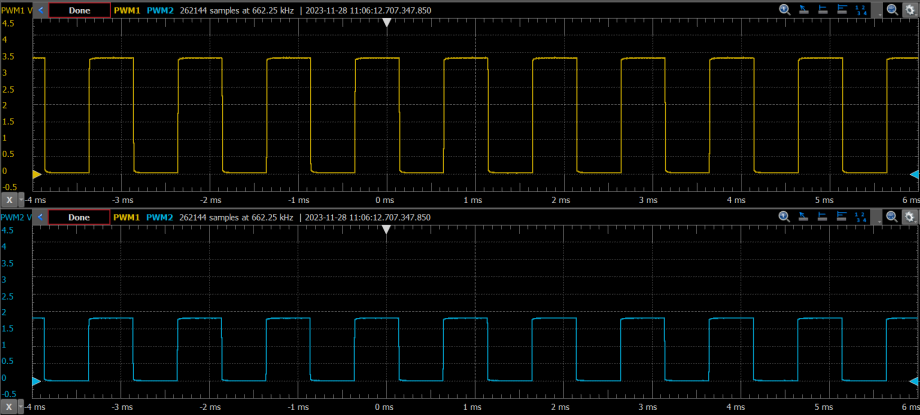
There are many common use cases for this functionality of the MVIO module, such as basic motor and LED control. The figure below shows how the output of two different PWM modules on the PIC18-Q24 device family differ between voltage domains. In this example, the microcontroller VDD supply pin is connected to 3.3V, and the VDDIO2 supply pin to 1.8V. Both PWM modules were set up the same, except that PWM1 was configured to output on a non-MVIO pin on the VDD domain and PWM2 to an MVIO pin on the VDDIO2 domain, shown in the figure below as the amplitudes of each PWM signal correspond directly to the voltage supplied for each respective domain. Although this example was demonstrated on the PIC18-Q24 device family, the same principle applies to all PIC and AVR devices with MVIO.