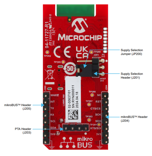
5 Getting Started with WINCS Add on board
The WINCS02 Add On Board supports one modes of operation:
- Host Companion mode – Using a host MCU board with mikroBUS socket via mikroBUS interface

The WINCS02 Add On Board can also be used with the host MCU boards using mikroBUS sockets with the control interface. The following table shows how the pinout on the WINCS02 Add On Board mikroBUS interface corresponds to the pinout on the WINCS02 Module.
Note:
- To operate WINCS02 Add On Board in Host Companion mode, ensure to place the jumper cap on J201.2, J201.3, as illustrated in the above image.
- Do not use Type-C USB cable in Host Companion mode.
| Pin Number | Pin on mikroBUS Header | Pin Description of mikroBUS Header | Pin on WINCS02PC Module(1) |
|---|---|---|---|
| 1 | AN | Analog input | NC |
| 2 | RST | Reset | MCLR |
| 3 | CS | SPI Chip Select | PA3/UART1_CTS |
| 4 | SCK | SPI Clock | NC |
| 5 | MISO | SPI host input client output | NC |
| 6 | MOSI | SPI host input client input | PA4/UART1_RTS |
| 7 | +3.3V | 3.3V power | +3.3V from host MCU socket |
| 8 | GND | Ground | GND |
| 9 | GND | Ground | GND |
| 10 | +5V | 5V power | NC |
| 11 | SDA | I2C Data | PA9_I2C_SDA |
| 12 | SCL | I2C Clock | PA8_I2C_SCL |
| 13 | TX | UART transmit | PA5_UART1_TX |
| 14 | RX | UART receive | PA1_UART1_RX |
| 15 | INT | Hardware interrupt | PA6_IRQ |
| 16 | PWM | PWM output | PB2_INT0_TMS_WAKE |
Note:
- For more details on the WINCS02 Module pins, refer to the WINCS02 Wi-Fi Module Data Sheet (DS70005544)
- The WINCS02 moduke does not support UART1 interface which is available on the mikroBUS interface.
