
6 Observe the Output on the MPLAB Data Visualizer
- After building the application and
completing the programming, open the MPLAB Data Visualizer by clicking the
highlighted icon below.
Figure 6-1. Launch the MPLAB Data Visualizer 
- Configure the serial port setup of
the PIC32CM LS00 Curiosity Nano+ Touch Evaluation Kit by clicking the Gear
icon shown below.
Figure 6-2. Serial Port Setup 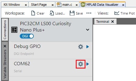
- Set the 115200 as baud rate in the
COM setting.
Figure 6-3. Baud Rate Configuration 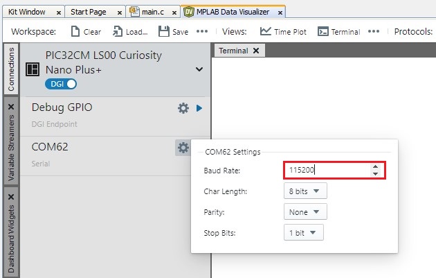
- Open the Serial Port of the PIC32CM
LS00 Curiosity Nano+ Touch Evaluation Kit by clicking the Play icon as shown
below.
Figure 6-4. Opening the Serial COM Port 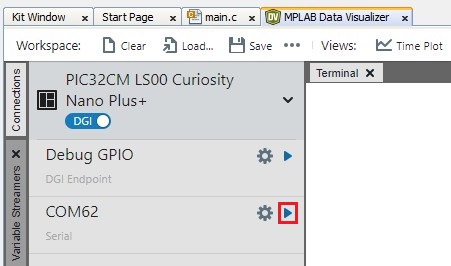
- Click Send to Terminal to view
the serial console message, and then click Close.
Figure 6-5. Select the Terminal Option 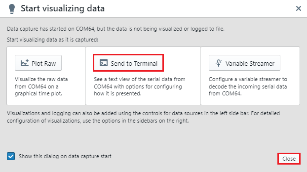
- Open the command prompt and navigate
to the following location: C:\Program
Files\Microchip\MPLABX\v6.20\mplab_platform\mplab_ipe.Note: The PIC32CM LS00 Curiosity Nano+ Touch Evaluation Kit has no Reset button to reset the MCU. To reboot the board, the
resetcommand is sent to the nEDBG to reset the MCU with the help of MPLAB IPECMD. - Run the following command to reset
the PIC32CM LS00 Curiosity Nano+ Touch Evaluation
Kit.
ipecmd.exe -P32CM5164LS00048 -TPNEDBG -OKFigure 6-6. Resetting the PIC32CM LS00 Curiosity Nano+ Touch Evaluation Kit - Observe the startup console message on the MPLAB Data Visualizer and the LED1 will
toggle on the PIC32CM LS00 Curiosity Nano+ Touch Evaluation Kit.
Figure 6-7. Startup Console Message 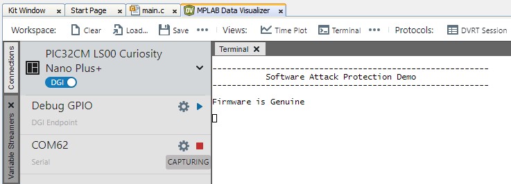
Figure 6-8. LED1 Toggling on PIC32CM LS00 Curiosity Nano+ Touch Evaluation Kit - Press the SW1 button on the PIC32CM
LS00 Curiosity Nano+ Touch Evaluation Kit to simulate a software attack.
Figure 6-9. Simulation of Software Attack - Observe the console message of
software attack initiation on the MPLAB Data Visualizer.
Figure 6-10. Software Attack Initiation 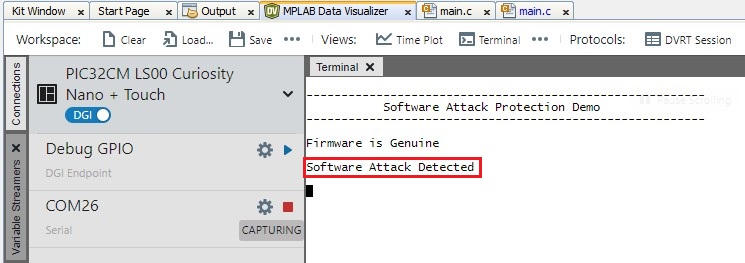
- Once the RTC timeout is reached,
Secure Application starts the verification of Non-Secure firmware. If the
verification fails, the genuine copy of the Non-Secure firmware will be programmed
on the Non-Secure Flash region.
Figure 6-11. Non-Secure Firmware Verification 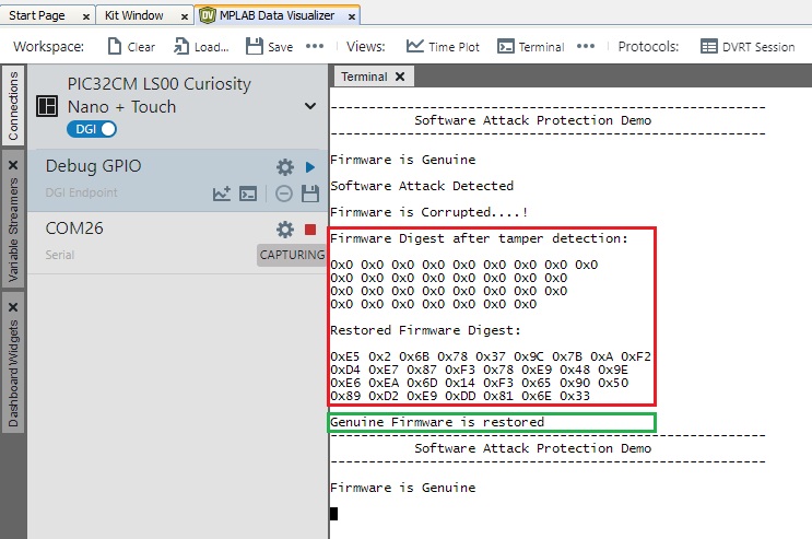 Note: After successfully programming a genuine copy, the secure application initiates a software reset.