
3.9.1 BLDC Block Commutation using dsPICDEM MCLV-2 Development Board with SAME54 Motor Control PIM
Description
This application run the Block Commutation algorithm for Brushless Direct Current (BLDC) motor with the help of the dsPICDEM MCLV-2 Development Board with SAME54 Motor Control PIM.
Modules/Technology Used
- Peripheral Modules:
- NVMCTRL
- EVSYS
- NVIC
- PORT
- TC
- EIC
- TCC
- ADC
- PDEC

Hardware Used
Optional:
- USB to RS-232 Converter
Software/Tools Used
This project has been verified to work with the following versions of software tools:
Refer Project Manifest present in harmony-manifest-success.yml under the project folder firmware/src/config/mc_bldc_block_commutation_dspicdem_mclv2_atsame54_pim/.
- Refer the Release Notes to know the MPLAB X IDE and MCC Plugin version.
Because Microchip regularly updates tools, occasionally issue(s) could be discovered while using the newer versions of the tools. If the project does not seem to work and version incompatibility is suspected. It is recommended to double-check and use the same versions that the project was tested with. To download original version of MPLAB Harmony v3 packages, refer to document How to Use the MPLAB Harmony v3 Project Manifest Feature (DS90003305).
Setup
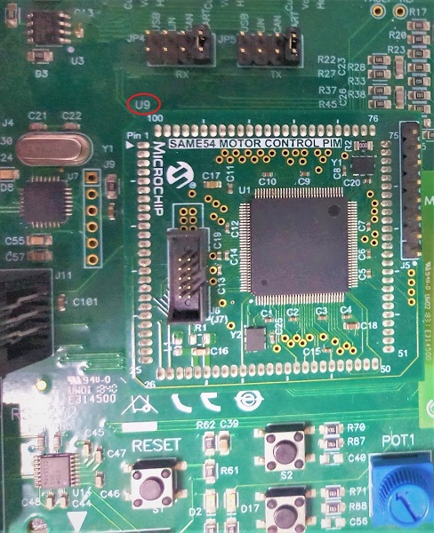
- Mount the ATSAME54 Motor Control PIM on
the U9 header of the dsPICDEM MCLV-2 Development Board as shown below.
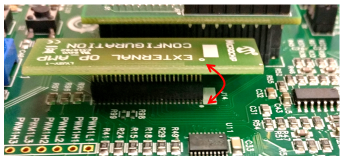
- Place the External Op-amp Configuration
Matrix board at J14.
- Connect the motor phases and hall
sensor interfaces. Hall and phase connections for Short Hurst motor are given below.

- Final hardware setup is shown
below.

Programming Hex File
The pre-built hex file can be programmed by following the below steps.
- Open MPLAB X IDE.
- Close all existing projects in IDE, if any project is opened.
- Go to File -> Import -> Hex/ELF File.
- In the Import Image File
window,
- Create Prebuilt Project,
- Click the Browse button to select the prebuilt hex file.
- Select Device as ATSAME54P20A.
- Ensure the proper tool is selected under Hardware Tool and click on Next button.
- Select Project Name and Folder,
- Select appropriate project name and folder and click on Finish button
- Create Prebuilt Project,
- In MPLAB X IDE, click on Make and Program Device button to program the device.
- Follow the steps in Running the Demo section below.
Programming/Debugging Application Project
- Open the project (mc_bldc_block_commutation/firmware/dspicdem_mclv2_atsame54_pim.X) in MPLAB X IDE
- Ensure J-32-SN:98xxxx is selected as hardware tool to program/debug the application
- Build the code and program the device by clicking on the Make and Program Device button in MPLAB X IDE tool bar
- Debugging the project can be done by clicking on the Debug Main Project button in MPLAB X IDE tool bar
- Follow the steps in Running the Demo section below
Running the Demo
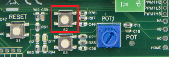
- Press the S2 switch on the
dsPICDEM MCLV-2 Development Board to start the motor.
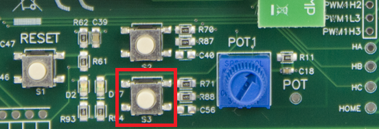
- Press the S3 switch to toggle
the motor direction.
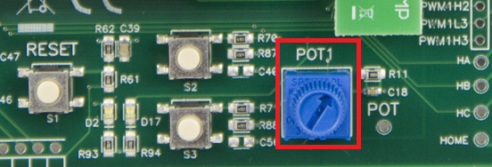
- Vary the potentiometer to change the
speed of the motor.
- Press the S2 switch again to
stop the motor.
Comments
- Reference Applications:
- This application demo builds and works
out of box by following the instructions above in Running the Demo section. If
the user needs to enhance/customize this application demo, should use the MPLAB Harmony
v3 Software framework. Refer links below to setup and build the applications using MPLAB
Harmony.
- How to Setup MPLAB Harmony v3 Software Development Framework (DS90003232).
- How to Build an Application by Adding a New PLIB, Driver, or Middleware to an Existing MPLAB Harmony v3 Project (DS90003253).
- Video - How to Set up the Tools Required to Get Started with MPLAB® Harmony v3 and MCC
- Create a new MPLAB Harmony v3 project using MCC
- Update and Configure an Existing MHC-based MPLAB Harmony v3 Project to MCC-based Project