
5.2 Xplained Pro Connections
Some Microchip development boards support only the Xplained Pro extension headers. Through use of an adapter board, the 2-lead µVSFN socket board can still be used. The figure below shows the full assembly of the 2-lead µVSFN socket board, the ATMBUSADAPTER-XPRO and an ATSAMD21-XPRO Development board.
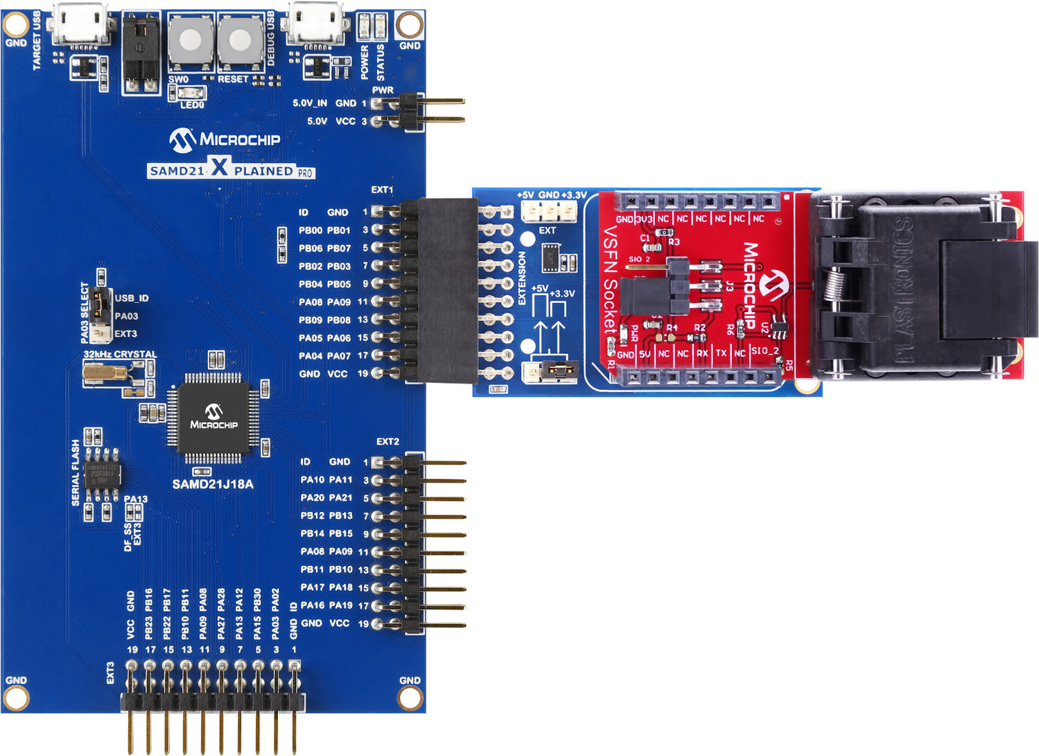
How to Connect the 2-Lead µVSFN to an Xplained Pro Host Board
- Configure the EV98D91A to the desired mode as specified in Modes of Operation.
- Connect the ATMBUSADAPTER to the 2-lead µVSFN as shown in Figure 5-2.
- Connect the combined ATMBUSADAPTER and 2-lead µVSFN to one of the XPRO extension connectors on the host board. EXT1 is used in Figure 5-2.
- Connect the USB cables to the TARGET USB Port and the DEBUG USB Port and the host system.
- Invoke the appropriate software development tools for the application.
Important: The EV98D91A
kit must be connected to EXT1 if the device supports the SWI-PWM protocol or EXT2 or
EXT3 for a product that supports the SWI protocol.