
5 Appendix: Ethernet Link Testing Techniques
This appendix explains various methods to verify the PHY link status and ensure that software observations align with the electrical signaling.
With Ethernet Copper PHYs, the PHY chip is responsible for establishing a link with the connected partner. The PHY will then report the link status back to the processor or switch where the Media Access Controller (MAC) resides.
The following are various hardware and software methods to configure various link connections and the expected electrical signals for each link state. The diagram below represents the general PHY link procedure.
The PHY needs to be configured for the link procedure to flow. It can force the speed for known network configurations and a desire for fast link times. Alternatively, it can be configured to auto negotiate with the various link speed capabilities it can advertise. For unknown network configurations, this is the recommended method.
Forced Link Speeds
10BASE-T Links
The standard Basic Control register of most PHYs can be used to set the port speed manually. To set the PHY into 10BASE-T mode, ensure the Duplex Mode bit is set to Full Duplex, and the Speed Select bits are set to 00b. For many PHYs, this would mean a value of 0x0100 is written to the control register. It is often recommended to reset the PHY for these settings to take effect, so the full process would be:
- Write 0x8100 to the Basic Control Register (Register 0).
- Read the Basic Control Register and confirm 0x0100 is read back (reset has cleared).
- Read PHY Control Register (not applicable in all PHYs) to confirm the PHY Link Status.
If using the standard Linux driver, the speed configuration is more abstracted away from the raw register read and writes. The following command would put the PHY into 10BASE-T mode:
Ethtool -s eth0 speed 10 duplex full autoneg off
If using the Microchip StaX command line functions:
# conf t // Enter configuration mode
(config)# int g 1/1 // Prepare to configure Port 1 of LAN8814
(config-if)# speed 10 // Set to Force 10Mbps and Full duplex
(config-if)# debug phy read 0 // Read the status to ensure configuration successful
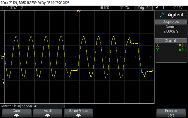
To confirm a successful 10BASE-T connection, the captured data should have random NLPs or the data packets should have the following shape:
100BASE-TX Links
The same registers can be used to force the link to 100M speed. Instead of 0x0100, it should be 0x2100 for the Basic Control Register, setting the Speed Select to 01b instead of 00b for 10M mode. It is often recommended to reset the PHY for these settings to take effect, so the full process would be:
- Write 0xA100 to the Basic Control Register (Register 0).
- Read the Basic Control Register and confirm 0x2100 is read back (reset has cleared).
- Read PHY Control Register (not applicable in all PHYs) to confirm the PHY Link Status.
If using the standard Linux driver, the speed configuration is more abstracted away from the raw register read and writes. The following command would put the PHY into 100BASE-Tx mode:
ethtool -s eth0 speed 100 duplex full autoneg off
If using the Microchip StaX command line functions:
# conf t // Enter configuration mode
(config)# int g 1/1 // Prepare to configure Port 1 of LAN8814
(config-if)# speed 100 // Set to Force 100Mbps and Full duplex
(config-if)# debug phy read 0 // Read the status to ensure configuration successfull
Port Addr Value 15 8 7 0
1 0x00/0 0x2100 0010.0001.0000.0000
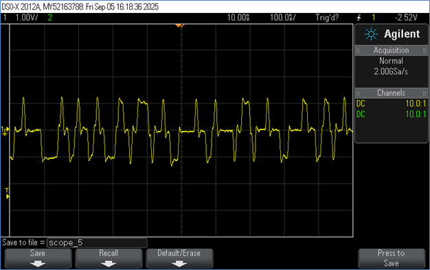
To confirm a successful 100BASE-TX connection, the captured data should have random scrambled data regardless of whether it is Idle or a data packet:
Auto Negotiation
Due to the uncertainty of what device will be connected to the PHY, most PHYs default to negotiate with the Link Partner to determine the fastest compatible speed. How the PHY negotiates is managed through the Auto-Negotiation registers. Once the Auto-Negotiation bit is set in the Basic Control register, the Speed Select and Duplex bits are ignored and the PHY references the Auto-Negotiation Advertisement register.- Write the desired settings to the Auto Negotiation Advertisement Register
- Write 0x9000 to the Basic Control register.
- Read the Basic Control register and confirm 0x1000 is read back.
- Read the Basic Status register and confirm the Auto-negotiation Complete bit is set.
- Read the various PHY Control register and 1000BASE-T Control (where applicable) registers to check the full link status.
To configure the port in Linux use the following command:
ethtool -s eth0 speed 100 duplex full autoneg on
If using the Microchip StaX command line functions:
# conf t // Enter configuration mode
(config)# int g 1/1 // Prepare to configure Port 1 of PHY
(config-if)# speed auto // Set to Auto Negotiation
(config-if)# debug phy read 0 // Read the status to ensure configuration successful
Port Addr Value 15 8 7 0
1 0x00/0 0x1140 0001.0001.0100.0000
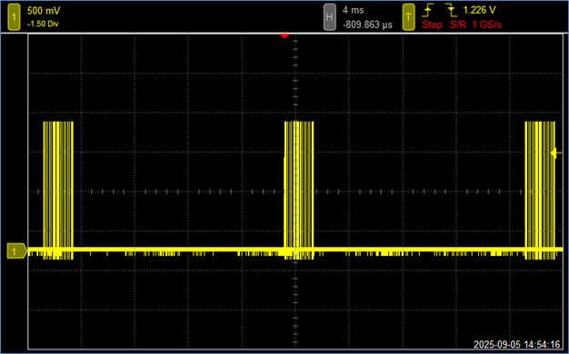
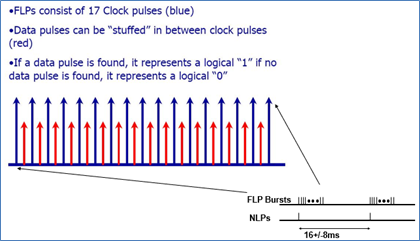
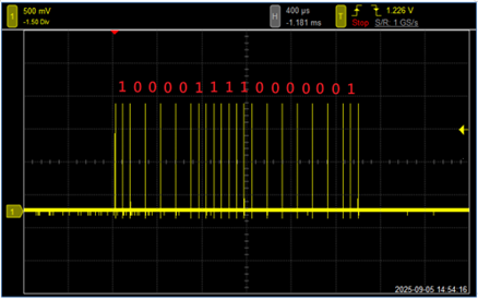
To check if Auto-Negotiation is happening, make sure that the PHY is NOT connected to a link partner, and check for the presence of Fast Link Pulses that signal the auto-negotiation process:
Checking Link Status
To check the link status of the PHY, the standard Basic Status register can be used. Bit 2 is the Link Status and bit 5 is the Auto-Negotiation Complete status.
The following are high level examples of how various software tools indicate the Link Status of the PHY:
Linux:
# ethtool eth0
Settings for eth0:
        Supported ports: [ TP MII ]
        Supported link modes:   10baseT/Half 10baseT/Full
                                100baseT/Half 100baseT/Full
                                1000baseT/Half 1000baseT/Full
        Supported pause frame use: Symmetric Receive-only
        Supports auto-negotiation: Yes
        Advertised link modes:  10baseT/Half 10baseT/Full
                                100baseT/Half 100baseT/Full
                                1000baseT/Half 1000baseT/Full
        Advertised pause frame use: Symmetric Receive-only
        Advertised auto-negotiation: Yes
        Speed: 1000Mb/s
        Duplex: Full
        Port: MII
        PHYAD: 0
        Transceiver: internal
        Auto-negotiation: on
        Link detected: yes
// Show PHY Link status from PHY Basic Status Register of PHY
# platform debug allow
# debug api phy interface GigabitEthernet 1/1
PHY   0
=======
Port:0   Family:Indy   Type:8814   Rev:3   MacIf:QSGMII
REG_NAME                                        PORT_NO PAGE_ID REG_ADDR   VALUE
Main Page Registers
Basic Control Register                       :  0x00  0x00   0x0000     0x00001040
Basic Status Register                        :  0x00  0x00   0x0001     0x0000796d
Device Identifier 1 Register                 :  0x00  0x00   0x0002     0x00000022
Device Identifier 2 Register                 :  0x00  0x00   0x0003     0x00001663
// Show PHY Link status from high level iStax APPL
# show interface GigabitEthernet 1/1 status	//Plug-in Ethernet cable in PHY Port 1
Interface  Mode     Speed   Aneg       Media Type SFP Family   Link    Operational Warnings
---------- -------- ------- ---------- ---------- ------------ ------- --------------------
Gi 1/1     Enabled  Auto    Yes        RJ45       N/A          1Gfdx

# show interface GigabitEthernet 1/1 status	//Unplug-in Ethernet cable in PHY Port 1
Interface  Mode     Speed   Aneg       Media Type SFP Family   Link    Operational Warnings
---------- -------- ------- ---------- ---------- ------------ ------- --------------------
Gi 1/1     Enabled  Auto    Yes        RJ45       N/A          Down