
4 Appendix: PHY Low Level Management Techniques
Ethernet management interface specifications
Ethernet physical layer devices (or PHYs) are attached to Ethernet MACs through different versions of Media independent interfaces (xMII). However, the xMII is only the data path. PHY management is done separately through a two-wire serial interface called a MII management interface (MIIM or MDIO interface) in IEEE 802.3 clause 22 (and later extended in clause 45). The two management interfaces can both be called serial management interfaces (SMI interface). MIIM, MDIO and SMI are often used interchangeably to describe this interface.
Clause 22 Interface
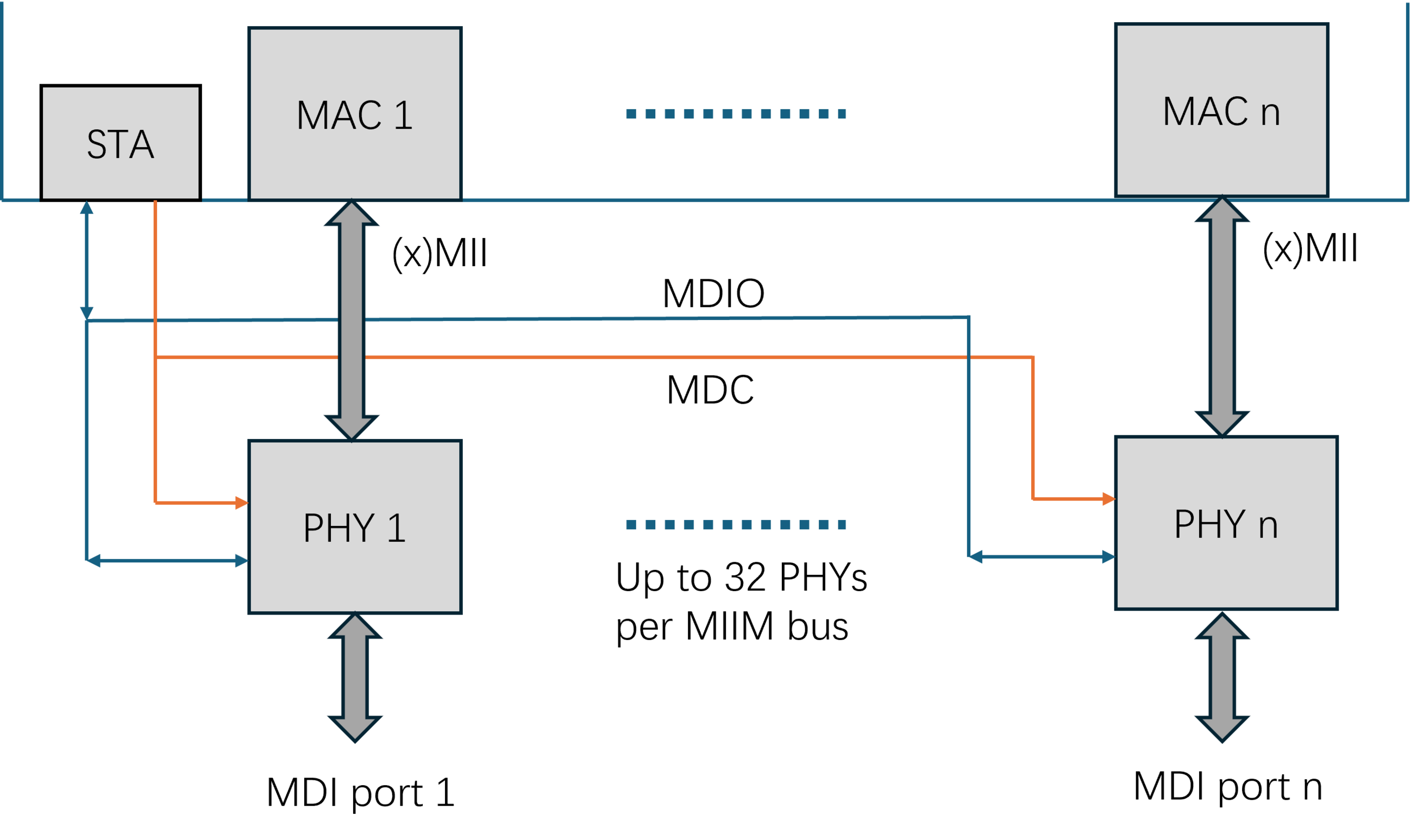
The MIIM interface is specified in IEEE 802.3 clause 22 for 10M, 100M and 1G PHY devices. Figure 4-1 shows the connection between an Ethernet MAC and PHY through xMII (can be MII, RMII, GMII, SGMII, QSGMII, etc.) and MIIM interfaces.
The STA (station management entity) manages all the PHY on this two-wire management bus through reading/writing to a series of 16-bit registers in each PHY. The STA addresses each PHY through a 5-bit PHY address field and addresses each register in that PHY through another 5-bit register address field in the management frame. Therefore, the STA can manage up to 32 PHYs with up to 32 registers in each PHY on the same MIIM bus.
The MIIM interface consists of two signals – MDC and MDIO. MDC is a clock signal sourced by the STA to the PHYs as the timing reference for transfer of the information on the MDIO signal. MDIO is a bidirectional signal between the PHY and the STA. It is used to transfer control information and status between the PHY and the STA. MDIO is driven through three-state circuits that enable either the STA or one of the PHY to drive the signal.
Measuring the Ethernet Management interface signals
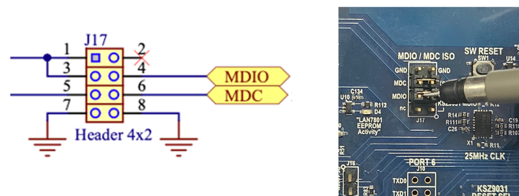
As shown in the system diagrams, each MIIM (or MDIO) bus connects between a STA and a number of PHYs. A STA can be a switch or a CPU depending on the design. Multiple MIIM (or MDIO) buses can exist on the same board with groups of the PHYs attaching to different MIIM (or MDIO) buses. Firstly, sort out the MIIM (or MDIO) bus structures in the design before measuring the signals. Then, find the best test points on the board to tap into the signals. Below are some possible measuring points for the MDC and MDIO signals:- Dedicated test points
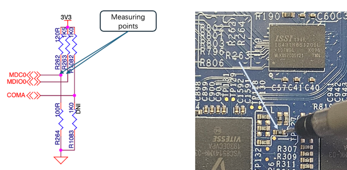
- Pull Up Resistors
Decoding Clause 22 Management Signals
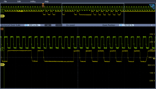
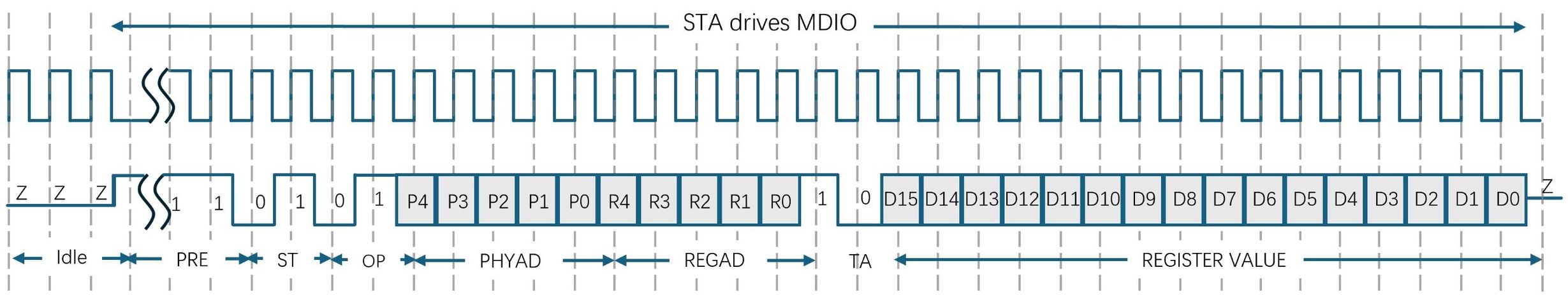
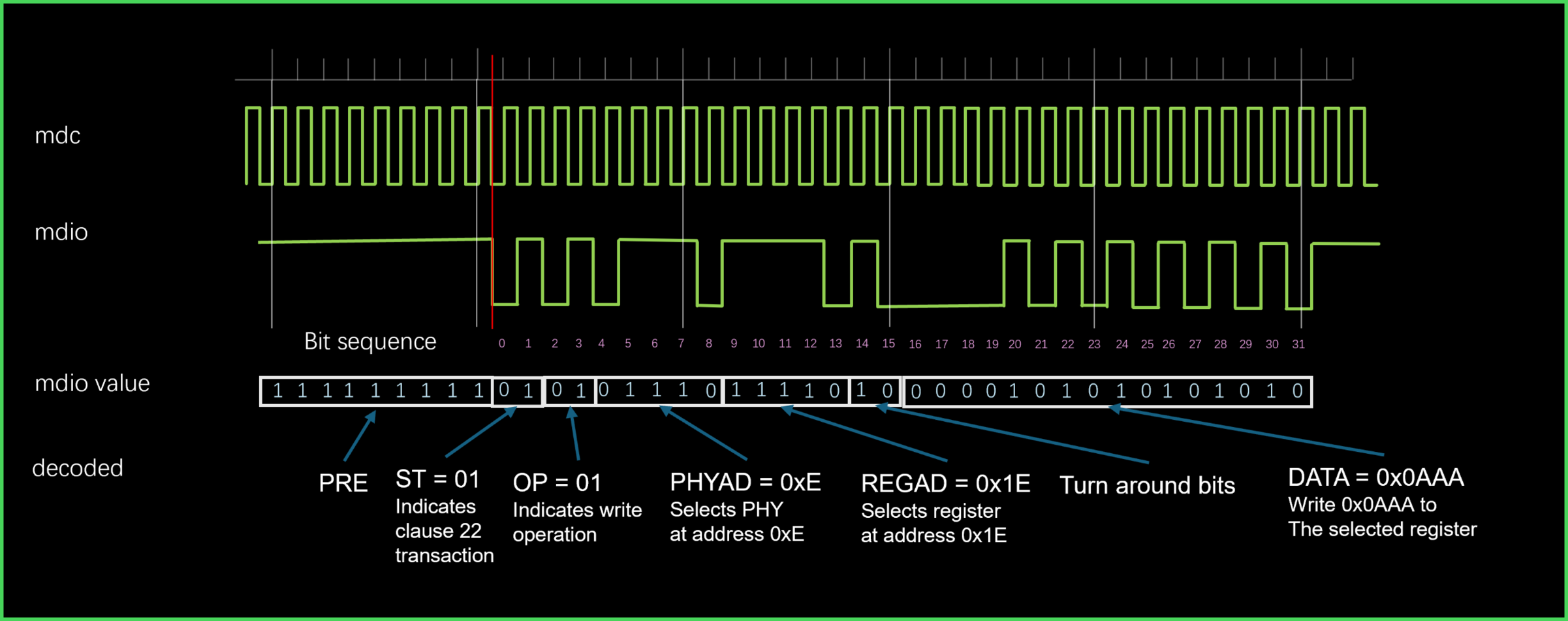
Data is transferred over the clause 22 MIIM interface using 32-bit frames with an optional, arbitrary number of “1” as preamble (PRE). “01” marks the start of frame (ST) followed by a 2-bit Opcode field (OP) where “10” indicates a read and “01” indicates a write operation. A 5-bit PHY address (PHYAD) field selects the PHY device, and another 5-bit register address (REGAD) specifies the register to be read or written. After a 2-bit turn around (TA) period the STA drives the 16-bit data for a write operation or the selected PHY (selected by the 5-bit PHY address field) drives the 16-bit data as a response to read operation.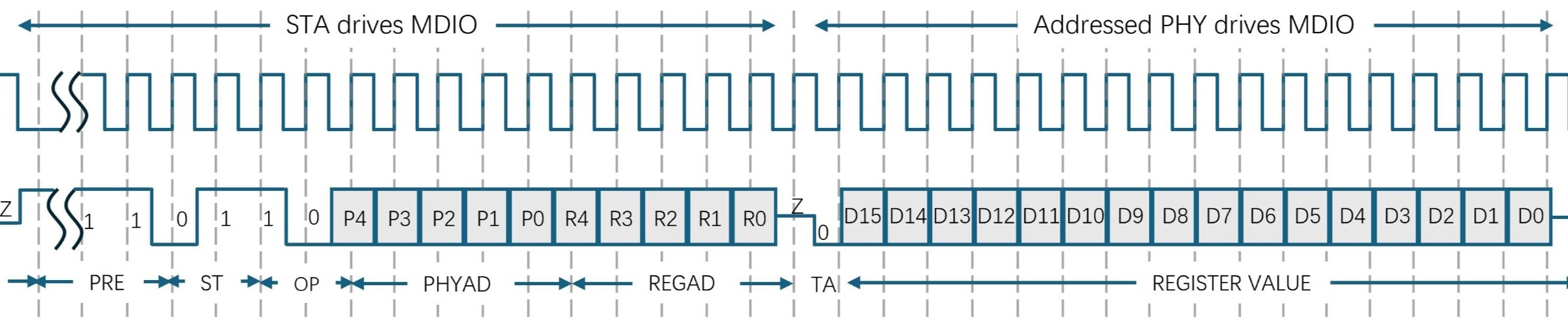
Methods to read/write PHY registers
Normally, the STA polls various status registers of each PHY periodically, so MIIM (or MDIO) read waveforms can be observed without the need of any command at the STA. However, if a specific capture is desired with specific PHY, MMD, or register addresses, manual control is needed from MIIM (or MDIO) read/write tools. Those tools are highly dependent on different hardware and software environments. In below sections are some examples on Microchip StaX Ethernet switch application and Generic Linux switch/PHY drivers.
PHY read/write tools in ISTAX
- Clause 22 PHY register read/write commands
Clause 22 PHY register read/write commands are placed in the debug command group, need to be enabled. The following commands are needed, the warnings can be ignored.
# platform debug allow
WARNING: The use of 'debug' commands may negatively impact system behavior. Do not enable unless instructed to. (Use 'platform debug deny' to disable debug commands.)
NOTE: 'debug' command syntax, semantics and behavior are subject to change without notice.
Get into the configuration mode
# configure terminal
Each physical port is mapped to an interface in the switch. Set the switch interface where the Clause 22 PHY registers will be manipulated. The PHY address to switch interface mapping is already done at compile time so once specified via the interface, the software will automatically generate the PHY address field in the MIIM frame. Below, the interface selected is GigabitEthernet 1/1
(config)# interface GigabitEthernet 1/1
Use “debug phy read REGAD” command to read from register 1 of the PHY that is attached to interface GigabitEthernet 1/1
(config-if)# debug phy read 1
Use “debug phy write REGAD value” command to write 0x0100(force 10M full duplex) to register 0 of the PHY that attached to interface GigabitEthernet 1/1
(config-if)# debug phy write 0 0x0100
PHY read/write tools via Linux
There are several Linux utilities that can be run from the terminal prompt of the Linux host. Among them are ethtool and phytool.
To use any of these tools on the Linux host, the tools must be installed on the host. To check whether a tool is installed simply type in its name at the terminal prompt. If -sh: <tool>: not found is displayed then the <tool> is not available.
Ethernet interfaces must also be setup before ethtool and phytool can be used. The commands below sets eth0 up
~# ip link set dev eth0 up
While ethtool provides extensive options to query or control network driver and hardware setting for an Ethernet interface, phytool is specifically tailored for phy register read and write through MIIM (or MDIO) interface with explicitly specified address fields. Therefore phytool is recommended for MIIM (or MDIO) interface test.
Syntax :
phytool read IFACE/ADDR/REG
phytool write IFACE/ADDR/REG <0-0xffff>
phytool print IFACE/ADDR[/REG]
- For clause 22
IFACE is the eth interface
ADDR is the 5-bit PHY address field in the range of <0-0x1f>
REG is the 5-bit register address field in the range of <0-0x1f>
The read and write commands are simple register level access commands. See below for read and write examples
~ # phytool read eth0/0/4 # Read PHY register 4 from eth0
~ # phytool write eth0/0/0 0x0100 # write 0x0100 to PHY register 0 of eth0
The print command will pretty-print a register. When using the print command, the register address is optional. If left out, the most common registers will be shown. See below example.
~ # phytool print eth0/0
ieee-phy: id:0x01410eb1
ieee-phy: reg:BMCR(0x00) val:0x1140
flags: -reset -loopback +aneg-enable -power-down -isolate -aneg-restart -collision-test
speed: 1000-full
ieee-phy: reg:BMSR(0x01) val:0x7949
capabilities: -100-b4 +100-f +100-h +10-f +10-h -100-t2-f -100-t2-h
flags: +ext-status -aneg-complete -remote-fault +aneg-capable -link -jabber +ext-register