3.3 CI/CD 32-bit Example Flow
Follow the steps above to setup and execute the hardware-in the-loop feature for an 32-bit project using CI/CD wizard generated files.
Step 1. Extract Example Files
Find the example zip file with the PDF of this document posted on the MPLAB ICE 4 Breakout Board webpage.
Unzip and import the project sam_e54_xpro.X into MPLAB X IDE v6.00
or later.
The contents of the project are:
- MPLAB harmony project which demonstrates how to use the DMAC peripheral to do a memory-to-memory transfer
- CI/CD Wizard generated files:
- DockerFile
- JenkinsFile
mdb-hardware-script.txt
- Unity test runner files
The main.c file contains code for the application which uses a
software trigger to initiate a memory-memory transfer from the source buffer to the
destination buffer with 16-bit beat size and 32-bit beat size. The number of cycles
taken for the DMA transfer is measured using the System timer (SysTick) and reported
on the console. For details, see: DMAC memory transfer.
Step 2. Connect Hardware
Assemble the system as shown in the figures and table below.
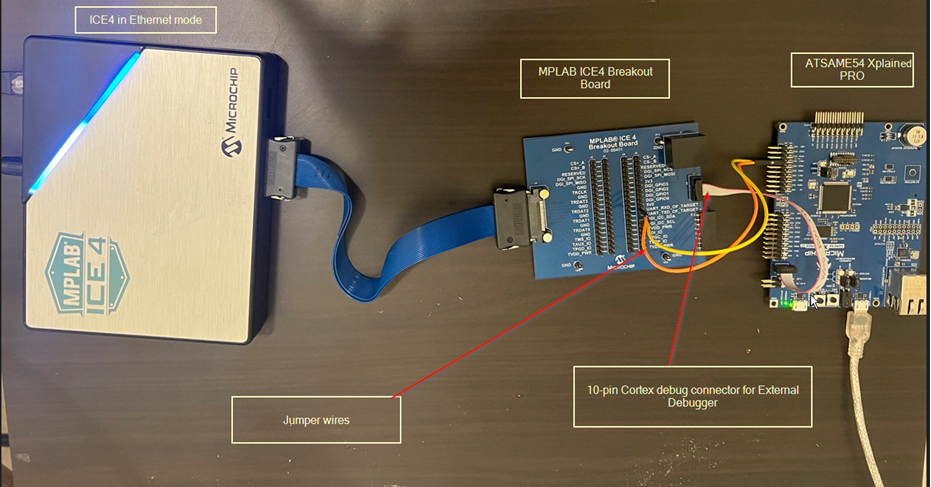
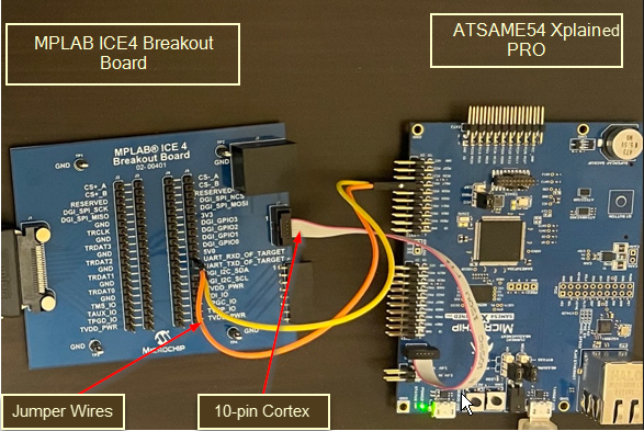
| MPLAB ICE 4 Breakout Board | ATSAME54 Xplained Pro |
|---|---|
| UART_RXD_OF_TARGET | PB17 (Extension Header EXT2) |
| UART_TXD_OF_TARGET | PB16 (Extension Header EXT2) |
| J7 | SAME54 SWD DEBUG |
Step 3. Update Generated Files
1. Update the network server license information into the Dockerfile as shown below.
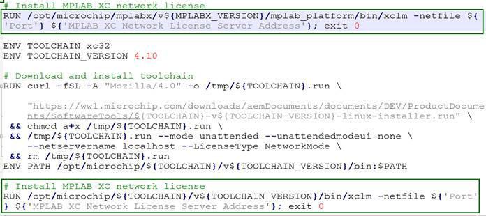
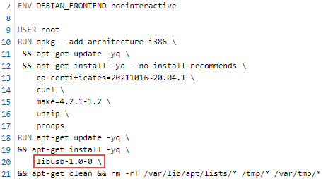
2. If needed, based on the Linux/MPLAB X IDE version, please install
additional packages from the Dockerfile, e.g libusb.so (see figure
below).
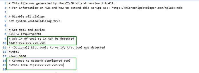
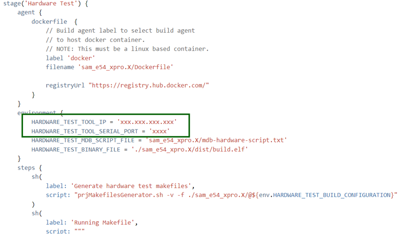
3. Update the IP address for MPLAB ICE 4 connected in Ethernet mode in the
mdb-hardware-script.txt file and the JenkinsFile (as shown
below).
Step 4. Add Project Files to Version Control
Add the project source code to a source control system (example: Subversion, CVS, or Git).
Make sure the Jenkins server supports your source control system and can access to your project repository.
Step 5. Create a Jenkins Pipeline
Create a Jenkins pipeline.
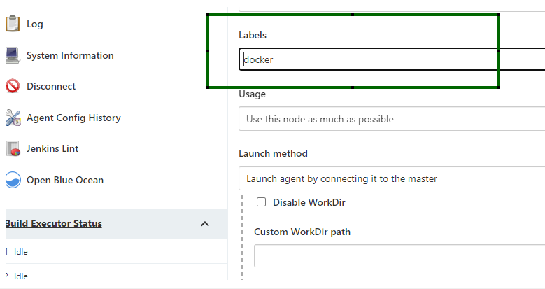
Edit the label of the Jenkins agent you are planning to run these tests with as ‘docker’ (see figure) or update the JenkinsFile with the label name based on your node label.
Make sure that the node you select to run the Jenkins Pipeline has Docker installed and running and is a Linux system.
Step 6. Execute the Pipeline
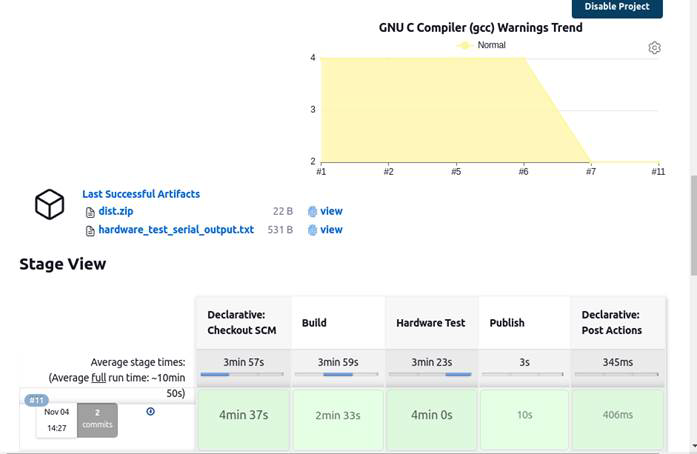
The pipeline job will execute all the stages (Build, Analyze, Hardware Test, etc.) as seen below.
When executing the ‘Hardware Test’ stage, the
mdb-hardware-script.txt file is executed.
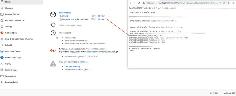
Step 7. View Execution Results
Once the Jenkins job is complete, the following files will be generated as a part of the post declarative action (see figure.)
The files are:
- Dist.zip – Collection of the build artifacts from the compiler. .hex-files, .elf-files and similar.
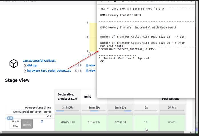
- Hardware_test_serial_output.txt – text file with the Unit test Pass/Fail results (see figure).
Optional: Customize Execution
For customizing the mdb-hardware.txt file with more commands
supported by the MDB tool, you can also refer the Microchip Debugger (MDB) User's
Guide (DS-50002102).
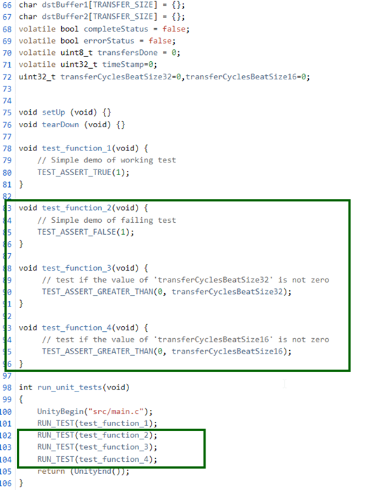
In the main.c file you can also add some additional assertions to
check what is expected to be true about your embedded system. Please see the example
code below where tests test_function_2,
test_funtion_3, and test_function_4 have been
added in main.c.
For more on rewriting your main.c and adding more advanced tests to
it, see: https://github.com/ThrowTheSwitch/Unity/blob/master/docs/UnityGettingStartedGuide.md.
The hardware_test_serial_output.txt generated after completion of the
Jenkins pipeline will look as seen below.