43.1 Comparator Overview
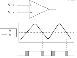
A single comparator is shown in Figure 43-1 along with the relationship between the analog input levels and the digital output. When the analog voltage at VIN+ is less than the analog voltage at VIN-, the output of the comparator is a digital low level. When the analog voltage at VIN+ is greater than the analog voltage at VIN-, the output of the comparator is a digital high level.

Note:
- The black areas of the output of the comparator represent the uncertainty due to input offsets and response time.

Note:
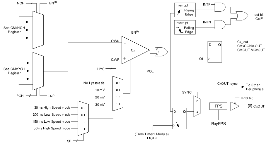
- When EN =
0, all multiplexer inputs are disconnected and the Comparator will produce a ‘0’ at the output.
