
1.1.2 Curiosity PIC32MZ EF 2.0 Development Board: Building and Running the OTA Bootloader Applications
Downloading and Building the Application
To clone or download this application from Github, go to the main page of this repository and then click Clone button to clone this repo or download as zip file. This content can also be download using content manager by following these instructions.
Path of the application within the repository is apps/ble/dual_bank/.
To build the application, refer to the following table and open the project using its IDE.
OTA Bootloader
| Project Name | Description |
|---|---|
| ota_bootloader/firmware/pic32mz_ef_curiosity.X | MPLAB X Project for Curiosity PIC32MZ EF 2.0 Development Board |
OTA Application
| Project Name | Description |
|---|---|
| ota_app/firmware/pic32mz_ef_curiosity.X | MPLAB X Project for Curiosity PIC32MZ EF 2.0 Development Board |
Setting Up Curiosity PIC32MZ EF 2.0 Development Board
- To run the demo, the following additional hardware are required:
- Short J2-1 and J2-2 using jumper in the RNBD451 Add-on Board
- Insert RNBD451 Add-on Board into mikroBUS Connector 1
- For programming and UART Console, connect a micro USB cable to the USB Debug port J700
Setting up the host scripts
- Refer to the OTA Bootloader Host Script Help for settings up python scripts which are used in order to update the application binary image
Running the Application
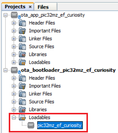
- Open the OTA bootloader project ota_bootloader/firmware/pic32mz_ef_curiosity.X in the IDE.
- Ensure that the ota_app/firmware/pic32mz_ef_curiosity.X is added as a
loadable project to OTA bootloader project.
- As the Dual Bank Flash memory may not have any valid binary required by OTA bootloader for the first time. Adding the ota_app as loadable allows MPLAB X to create a unified hex file and program both these applications in their respective memory locations based on their linker script configurations.
- Open the Terminal application (e.g., Tera Term) on the computer.
- Connect to the Serial COM port and configure the serial settings as follows:
- Baud: 115200
- Data: 8 Bits
- Parity: None
- Stop: 1 Bit
- Flow Control: None
- Build and Program the OTA bootloader application using the IDE.
- Once programming is done, OTA
bootloader starts execution and directly jumps to application space to run the
OTA application.
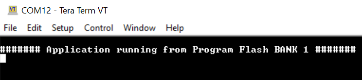
- LED1 starts blinking indicating that the OTA application is running
- Observe the below message
on console
- Go to the
<harmony3_path>/bootloader_apps_ota/apps/ble/dual_bank/ota_app/firmware/pic32mz_ef_curiosity.X/dist/pic32mz_ef_curiosity/production/
directory and open the command prompt to run the below
command.
python <harmony3_path>/bootloader_apps_ota/tools/ota_host_mcu_header.py -p 0x9D100000 -j 0x9D000200 -f pic32mz_ef_curiosity.X.production.bin
- This command adds OTA Host MCU Header to the application binary. If command executed successful then "image.bin is generated successfully" message display on the command prompt.
- Run the below
command.
python <harmony3_path>/bootloader_apps_ota/tools/ota_rnbd_header.py -f image.bin
- This command adds OTA RNBD Header to the image.bin and generates RNBD_image.bin application binary. If command executed successful then "RNBD_image.bin is generated successfully" message display on the command prompt.
- Refer to the Send application binary using MBD App to program RNBD_image.bin application binary to the target.
- Once Firmware Update is successful:
- LED1 still blinking indicating that the OTA application is running
- Observe the below message on console
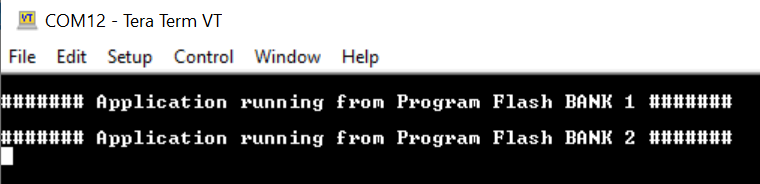
- Repeat Steps 9-10.
- Observe LED1 still blinking
- Observe message printed on console ####### Application running from Program Flash BANK 1 ####### or ####### Application running from Program Flash BANK 2 ####### alternatively