
1.1.26 SAM RH71 TFBGA Evaluation Kit: Building and Running the UART Bootloader Applications
Downloading and Building the Application
To clone or download this application from Github, go to the main page of this repository and then click Clone button to clone this repo or download as zip file. This content can also be download using content manager by following these instructions.
Path of the application within the repository is apps/uart_bootloader/.
To build the application, refer to the following table and open the project using its IDE.
Bootloader Application Specifics for SAM RH71 TFBGA Evaluation Kit
The SAMRH71 TFBGA Evaluation kits embed an external SST38VF6401 memory on the board. This UART bootloader application for SAMRH71 TFBGA Evaluation kit show how to configure the MH3 bootloader module and how to load a test application in this memory.
Test Application Specifics for SAM RH71 TFBGA Evaluation Kit
The test application is made to run at the base address of the external SST38VF6401 memory that is mapped at address 0x60000000 by default.
After writing the test application inside the external SST39VF040 memory using the bootloader application in internal Flash, it is possible to modify the boot memory selection using the SW5 switch. In this case, the SAMRH71 device will boot directly from the external SST39VF040 memory. In that case, the application will take more time to start because the clock and HSMC access timings are reconfigured after the execution of the startup sequence. The first initialization will be executed at default reset clock configuration and with the worst case timing on the HSMC peripheral.
The default generated code has been modified in the test application example to workaround this constraint when the SAMRH71 boot directly on the test application:
-
The watchdog is disabled directly in the Reset_Handler function: As is takes more time, the default watchdog time can expire before it is disabled in the application system initialization.
-
The ramfunc attribute is added to the HSMC initialization function that modifies the read and write timing for the memory. When the application is already executing and fetching instructions from the external memory, it is recommended executing the function that modifies the external memory configuration from a different memory. The ramfunc attribute will place and execute the HSMC initialization function in internal RAM.
Bootloader Application
| Project Name | Description |
|---|---|
| bootloader/firmware/sam_rh71_tfbga_sst38.X | MPLAB X Project for SAM RH71 TFBGA Evaluation Kit |
Test Application
| Project Name | Description |
|---|---|
| test_app/firmware/sam_rh71_tfbga_sst38.X | MPLAB X Project for SAM RH71 TFBGA Evaluation Kit |
Setting Up SAM RH71 TFBGA Evaluation Kit
-
Power the board using POWER USB connector
-
Connect the DEBUG USB port of the board to a computer using a micro USB cable.
-
Set the Boot mode bootstraps pins to internal Flash and disable ECC using dip switch SW4: (SW4.1 = 0, SW4.2 = 0, SW4.3 = 0)
Setting Up the Host Script
- Refer to the Bootloader Host Script Help for setting up the btl_host.py utility used to send the application binary from host PC
Running the Application
-
Open the test application project test_app/firmware/sam_rh71_tfbga_sst38.X in the IDE.
-
Build the project to generate the binary (Do not program the binary).
-
Open the bootloader project bootloader/firmware/sam_rh71_tfbga_sst38.X in the IDE.
-
Build and program the application on the SAMRH71 device using the IDE.
-
Run the btl_host.py from command prompt to program the application binary.
python <harmony3_path>/bootloader/tools/btl_host.py -v -i <COM PORT> -d samrh71tfbga_prom -a 0x60000000 -f <harmony3_path>/bootloader_apps_uart/apps/uart_bootloader/test_app/firmware/sam_rh71_tfbga_sst38.X/dist/sam_rh71_ek/production/sam_rh71_tfbga_sst38.X.production.bin -
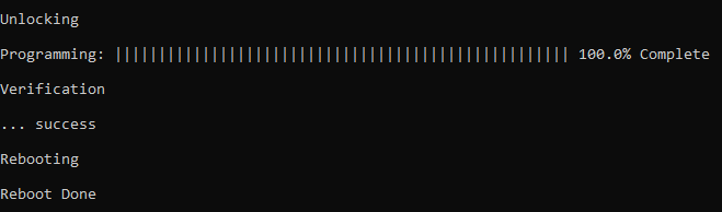
Following figure shows output of successfully programming the test application.
- Rebooting and Reboot Done messages in below output signifies that bootloading is successful
-
If above step is successful then the LED1 should start blinking.
-
Open the Terminal application (e.g., Tera Term) on the computer.
-
Configure the serial port settings as follows:
- Baud: 115200
- Data: 8 Bits
- Parity: None
- Stop: 1 Bit
- Flow Control: None
-
Reset or Power cycle the device.
-
LED1 should start blinking and the user should see below output on the console.
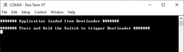
-
Press and hold the Switch SW0 to trigger Bootloader from test application and the user should see below output.
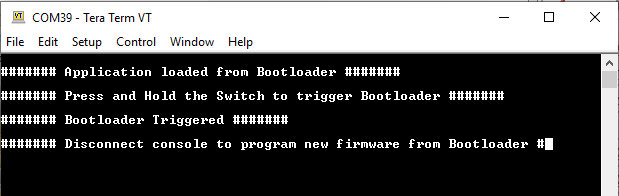
-
Repeat Steps 5-11 once and jump to Step 14.
- This step is to verify that bootloader is running after triggering bootloader from test application in Step 12
-
Press and hold the Switch SW0 and then press Reset button or Power cycle the device to force trigger bootloader at startup.
-
Repeat Steps 5-11 once.
- This step is to verify whether bootloader is triggered by switch press at reset
Additional Steps (Optional)
- To bootload any other application, refer to the Configuring an Application to Be Bootloaded for Cortex-M Based MCUs