4.6 Parallel Programming Description
High pin count Atmel AVR devices support the full Parallel Programming (PP) interface. This interface offers high speed programming, and also supports programming all fuse and lock bits in the AVR Device.
Extreme care should be taken if using PP mode to program an AVR device on an external target. The PP lines do not have level converters, so it is important that the target board is powered by the AVR Dragon VCC header, and not using its own power supply. In addition the AVR Dragon will apply 12V to the reset pin, so it is important that the target board is designed to handle 12V on this line.
The target voltage, i.e. the 5V from the VCC header must be applied to either pin 2 on the SPI header or pin 4 on the JTAG header. This is because the AVR Dragon must read the target voltage.
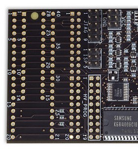
To avoid damaging the Target Board, the AVR Dragon or both, it is recommended to only use PP mode on devices placed in the 28/40 pin DIP socket on the AVR Prototype area on the AVR Dragon.

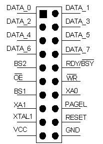
The HV_PROG header pinout is listed below. This is the standard pinout for about all Atmel AVR parts. However, the pinout on the HV_PROG header is slightly different for some parts. These exceptions are listed further down in this page.

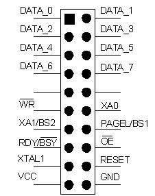
For ATtiny26/261/461/861 the HV_PROG header will have this pinout:

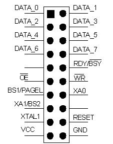
For ATtiny2313 the HV_PROG header will have this pinout:

See the Device Connection Sheet section for information on how to connect AVR Dragon for PP programming.
