
6.2 DALI Slave
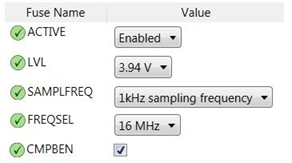
The following figure shows the MCU fuse settings. BOD is enabled with threshold level 3.94V. A 16MHz internal oscillator is selected as the MCU main clock source. The Compare B output is enabled for LED dimming. The PA5 multiplexing TCDOUTB function connects with the on-board LED as lighting demo in this application.
Pins PB3 and PB4 are used for DALI decoding/encoding in file dali_bit.c. EEPROM data memory in the ATtiny817 device is required to store DALI parameters. There are a total four pages in ATtiny817, the lower three pages store parameters and the last one acts as backup.