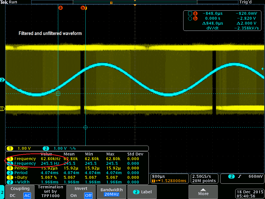
The following screen-shots are examples of sine wave signals generated by
Atmel ATtiny26 PWM for the configuration mentioned in Table 2-1.Figure 4-1. PWM Output and Sine
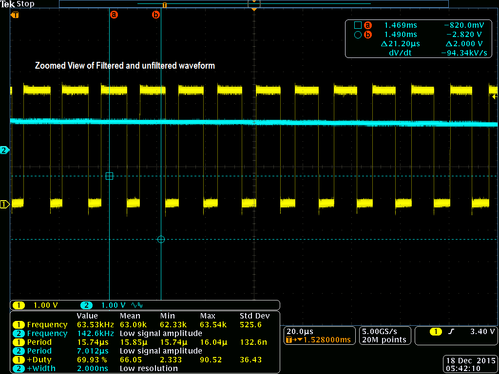
WaveFigure 4-2. PWM Output and Sine Wave –
Zoomed View
Note:
Waveform in blue color is
unfiltered PWM signal.
Waveform in Yellow color
is filtered Sine signal.
The screen-shots show the output on the OC1A pin, which is the digital
pulse modulated signal, and the filtered/shaped PWM signal. A simple RC filter is
used to shape the PWM signal to a sine wave – an analog signal where the amplitude
is controlled by the duty cycle of the PWM output. The RC filter used has R = 10kΩ
and C = 100nF, resulting in a filter crossover frequency of 1kHz, which will let the
low frequency sine wave pass while filtering out the high frequency PWM base.
The online versions of the documents are provided as a courtesy. Verify all content and data in the device’s PDF documentation found on the device product page.