As seen in the previous section, amplitude of the analog waveform is
directly proportional to duty cycle of PWM signal. So, if a sine wave is to be
generated, the duty cycle of the PWM signal has to be varied accordingly. In
ATtiny26, the OCR value determines the duty cycle of the PWM signal. In order to
control the variation in amplitude, the duty cycle has to be varied, thereby
generating a sine wave. The application uses a sine table that has the sample values
(duty cycle of PWM), which will be loaded at every Timer overflow. To generate a
sine table, the following parameters must be considered:
Table 2-1. Configuration
Parameters
Parameter
Value used in the application
CPUFreq
8MHZ
TimerFreq
16MHZ
TimerTop
255
PWMFreq
62.5kHz
SineFreq
~244Hz
CPUFreq: This is the frequency at which the
system is operated. In the application demonstrated, the CPU runs at 8MHz
using Internal RC Oscillator.
TimerFreq: This is the frequency at which the
Timer/Counter1 is operated. In the application demonstrated, 1MHz output of
Internal RC Oscillator acts as Timer1 PLL reference to generate a 64MHz
clock. This clock is then prescaled down to 16MHz to demonstrate the
prescaling capability of Timer/Counter1.
TimerTop: This is the Timer/Counter1 top value
that is one of the deciding parameters of PWM frequency. In the application
demonstrated 255 is loaded to 8-bit register OCR1C.
PWMFreq: This is the frequency of the PWM
output. It can be calculated by PWMFreq = TimerFreq /
TimerTop.
SineFreq: This is the frequency of Sine Wave
generated after passing the PWM signal to a Low-Pass filter. This can be
calculated by the formula, PWMFreq / TimerTop.
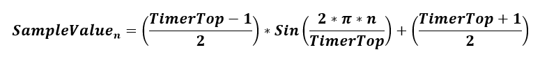
SampleValue: This is the instantaneous sample of
Sine Wave that will be loaded to OCR1A on every Timer overflow. The sample
value decides the duty cycle of PWM which in turn controls the amplitude of
the analog waveform (sine wave) generated. The formula to generate
SampleValue is shown as follows:
Note:
Here,
n is the number of samples in one cycle
of sine wave. It ranges from 0 to
TimerTop.
It has to be noted
that the CPU should be running fast enough to load the duty cycle
values to the OCR1A register after every Timer1 overflow.
Configurations to generate different frequencies of sine wave are listed
in the following table:
Table 2-2. Various Combinations to Generate Desired Frequency of Sine Wave
CPUFreq [MH]
TimerFreq [MH]
PWMFreq [kH]
SineFreq [Hz]
TimerTop
Number of CPU cycles before overflow
8
16
62.5
250
249
125
8
16
62.5
500
124
62.5
8
16
62.5
800
77
39
16
16
62.5
800
77
78
16
16
62.5
1000
62
63
16
16
62.5
1500
41
42
Note: The values shown in the table
has some restrictions on CPU speed and PWM speed. For more details, refer Interrupt Service Routine.
The online versions of the documents are provided as a courtesy. Verify all content and data in the device’s PDF documentation found on the device product page.