
3.3.2 Target Connection Pinouts
The programming connector pin functions are different for various devices and interfaces.
Refer to the following pinout tables for debug and data stream interfaces. Legacy 6-pin
RJ-11 cable can also be used, however target interfaces which use pins 1 (TMS/SWDIO) and
8 (TDI/MOSI) can not be programmed or debugged.
Note: Refer to the data sheet for the
device you are using as well as the application notes for the specific interface for
additional information and diagrams.
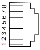
| MPLAB ICD 5 | DEBUG | TARGET4 | |||||||||||
|---|---|---|---|---|---|---|---|---|---|---|---|---|---|
| 8-Pin Modular Connector1 | Pin # | Pin Name | ICSP™ (MCHP) | MIPS EJTAG | Cortex® SWD | AVR® JTAG | AVR debugWIRE | AVR UPDI | AVR PDI | AVR ISP | AVR TPI | 8-Pin Modular Connector | 6-Pin Modular Connector |
 |
8 | TTDI | TDI | TDI | MOSI | 1 | |||||||
| 7 | TVPP | MCLR /Vpp | MCLR | RESET | RESET3 | 2 | 1 | ||||||
| 6 | TVDD | VDD | VDD/VDDIO | VDD | VTG | VTG | VTG | VTG | VTG | VTG | 3 | 2 | |
| 5 | GND | GND | GND | GND | GND | GND | GND | GND | GND | GND | 4 | 3 | |
| 4 | PGD | DAT | TDO | SWO2 | TDO | DAT3 | DAT | MISO | DAT | 5 | 4 | ||
| 3 | PGC | CLK | TCK | SWCLK | TCK | SCK | CLK | 6 | 5 | ||||
| 2 | TAUX | RESET | RESET/dW | CLK | RESET | RESET | 7 | 6 | |||||
| 1 | TTMS | TMS | SWDIO2 | TMS | 8 | ||||||||
|
|||||||||||||
| MPLAB® ICD 5 | DATA STREAM | TARGET2 | ||
|---|---|---|---|---|
| 8-Pin Modular Connector | PIC and AVR Devices | SAM Devices1 | 8-Pin Modular Connector | 6-Pin Modular Connector |
| Pin # | DGI UART / CDC | DGI UART / CDC | Pin # | Pin # |
| 8 | TX (target) | TX (target) | 1 | |
| 7 | 2 | 1 | ||
| 6 | VTG | VTG | 3 | 2 |
| 5 | GND | GND | 4 | 3 |
| 4 | 5 | 4 | ||
| 3 | 6 | 5 | ||
| 2 | RX (target) | 7 | 6 | |
| 1 | RX (target) | 8 | ||
|
||||
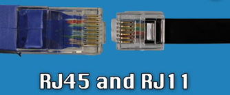
Note: For 6-pin RJ11 into 8-pin RJ45 socket, pins 1 and 8 are
lost.