1.1.3 Create First X2C Scope Harmony Project
Required Software
The instructions in this tutorial assume that you have already installed the following software:
- MPLAB X Integrated Development Environment
- MPLAB XC32/32++ C Compiler
Required Hardware
The following hardware is used to create a sample X2C Scope project. You can use these steps with different hardware platforms as well. While the overall process remains the same, some steps may vary slightly depending on the hardware:
- ATSAMC21 Motor Control Plugin Module
- dsPICDEM™ MCLV-2 Development Board
- 24 Volt power supply
Steps to Configure X2C Scope
- Launch the MCC from MPLAB® IDE (if not already opened) as shown below.

- Add TC1 from
Device Resources > Peripherals > TCinto the Project.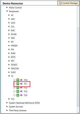
- Configure the timer period of TC1 to be the same as the sampling rate of the
X2CScope. Also, enable the period match interrupt. In this example, the timer
period is set to 50uS.

- Add X2Cscope component from
Device Resourcesto the Project graph as shown below: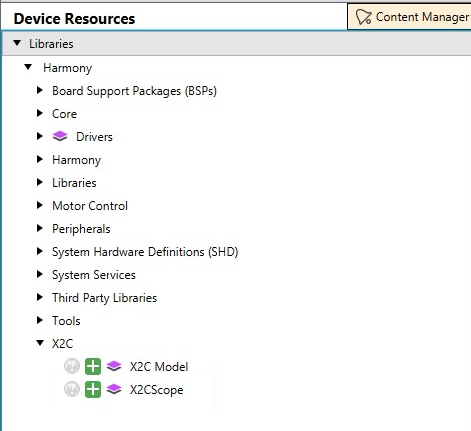
- Select the UART peripheral instance and the baud rate of the X2Cscope as shown
below:
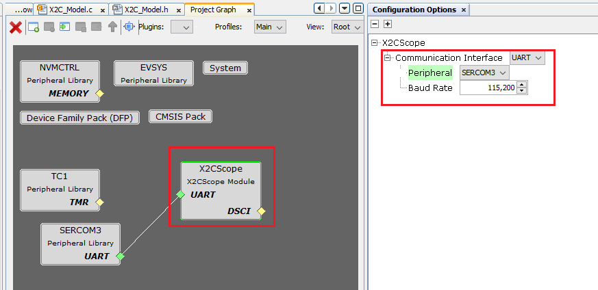
- Configure SERCOM with the following parameters:
- Map the UART TXD and RXD signals (this configuration requirement may vary from MCU to MCU). In this example, TXD is mapped onto PAD[0] and RXD is mapped onto PAD[1]
- Set Transmit and Receive enable
- Disable UART Interrupts (disabled by default upon connecting X2CScope to the UART peripheral)
- Parity Mode - None (set by default)
- Character Size - 8 (set by default)
- Stop Bit - 1 (set by default)
- Baud Rate - Recommended to set at 115200 (configured by default upon connecting X2CScope to UART peripheral)
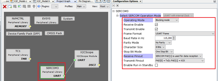
- Navigate to
Project Graph -> Plugins -> Pin Configurationto UART TX and RX pins. In this example, PA22 is configured as SERCOM3_PAD0 [mapped as TXD] and PA23 is configured as SERCOM3_PAD1 [mapped as RXD].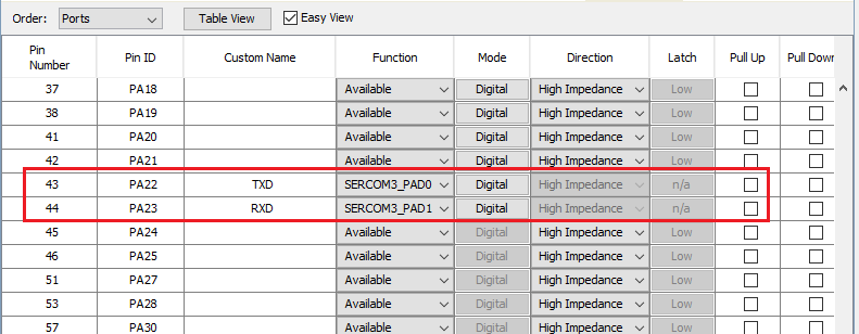
- Generate the configured example
project by clicking on
Generatewizard as shown below.
- Adding X2C Scope APIs in your application project:
- Navigate to
src -> main.cfile. - Add
X2CScope_Communicate()function call within the while(1) loop in the main function to establish communication between the target MCU and the X2C Scope plugin on the host PC. - Add
X2CScope_Update()to the desired periodic function to update global variables. In this example project, the update is done at TC1 interrupt sub-routine.uint8_t saw_tooth_wave; void TC1_PeriodicFunction ( TC_TIMER_STATUS status, uintptr_t context ) { saw_tooth_wave = ( saw_tooth_wave + 1u )& 0xFF; /** X2C Scope communicate */ X2CScope_Update(); } int main ( void ) { /* Initialize all modules */ SYS_Initialize ( NULL ); /** TC1 callback function for 50 uS ISR */ TC1_TimerCallbackRegister( (TC_TIMER_CALLBACK )TC1_PeriodicFunction, NULL ); /** Start TC1 timer */ TC1_TimerStart(); while ( true ) { /* Maintain state machines of all polled MPLAB Harmony modules. */ SYS_Tasks ( ); /** X2C Scope communicate */ X2CScope_Communicate(); } /* Execution should not come here during normal operation */ return ( EXIT_FAILURE ); } - Navigate to
Project Properties > Loadingand check "Load symbols when programming or building for production (slows process)" option as shown below: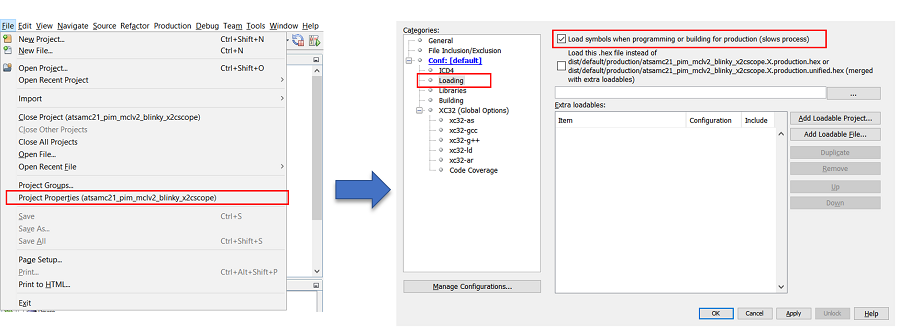
- Navigate to
- Clean Build the project.

- Program the project into the target MCU.

- Run the X2C Scope:
- Launch X2CScope plugin:
Tools > Embedded > X2CScope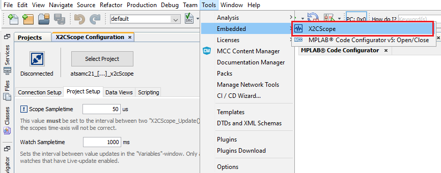
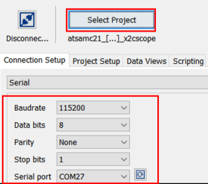
- Connect the X2C Scope project:
- Select relevant MPLAB X Project
- Set Baud Rate same as UART channel - 115200 (recommended)
- Set Data bits - 8
- Set Parity - None
- Select relevant COM Port
- Project set-up:
- Set Scope Sample time to match timer period which executes X2CScope_Update() at a fixed rate
- Set Watch Sample time
- Click on "Set Values"
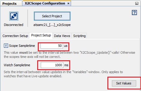
- Establish Connection by connecting "Disconnect/Connect" Toggle button.
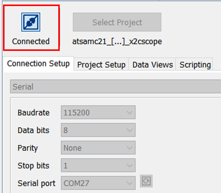
- Using Scope View:
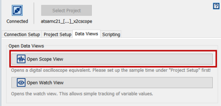
- Add the desired global variable to the corresponding channel and
click "Sample".
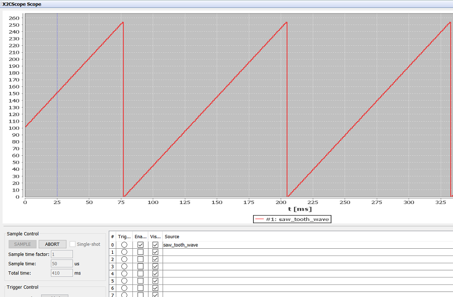
- Add the desired global variable to the corresponding channel and
click "Sample".
- Using Watch View:
- Launch X2CScope plugin:
