5.3 Avoiding PIO (Parallel Input/Output) Conflicts on the SAM9X60-Curiosity Board
The .dtsi file defines all the device's peripherals, but conflicts may arise between two peripherals when related to the specific board configuration. These conflicts can be identified by analyzing the board’s schematic, as illustrated below.
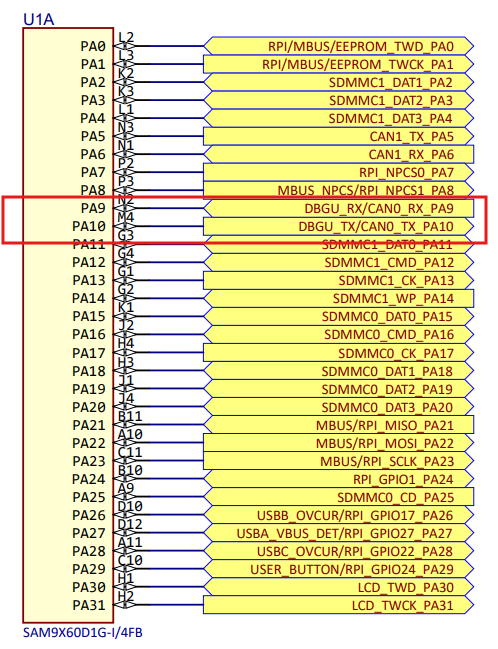
The schematic shows that CAN0 shares the same pin configuration as DBGU on pins PA9 and PA10. Therefore, to use DBGU as the serial console, CAN0 must be disabled in the board-specific Device Tree Source (.dts) file, and only the DBGU should be enabled.
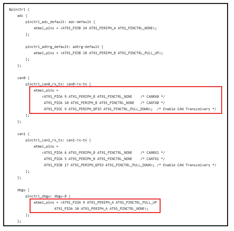
The following figure shows modifications that override the .dtsi file by disabling CAN0 and enabling only the DBGU functionality.
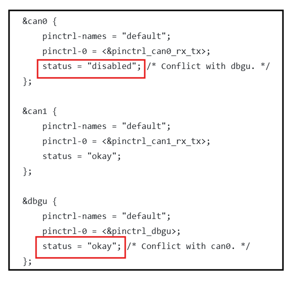
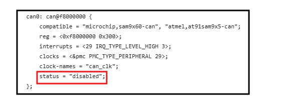
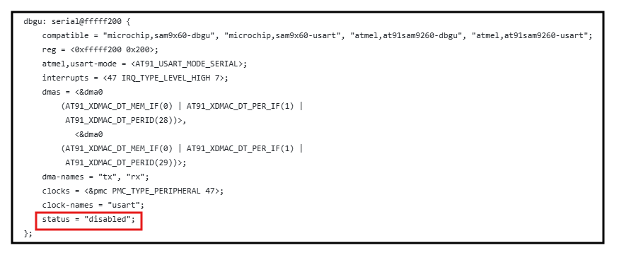
Both CAN0 and DBGU are assigned the same pins in the pin configuration under the atmel,pins property. To use CAN0, set the status of CAN0 to 'okay' in the .dts file and set the status of DBGU to 'disabled'.