
5.1 Defining a Node for the SAM9X60-Curiosity Board
The device tree structure should include a root node (/) that represents the System on Chip (SoC) and contains all relevant nodes, such as those describing the SoC details, CPU, memory, bus interfaces, clocks, APB buses and peripherals such as USB.
Each node in a Device Tree Source (.dts) file can be defined using a structured format enclosed within curly braces ({}). Each node represents a device or component within an embedded system. The node name is followed by the node properties, which are key-value pairs that describe the node's attributes, such as its compatible strings, registers and clock information. Child nodes can be nested within parent nodes to represent subcomponents or dependencies.
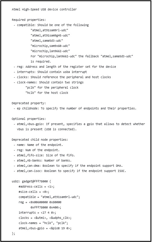
The following figure shows a usb0 gadget node from the SAM9X60.
The compatible property associates the gadget peripheral node with the USB host driver.
The DT binding provides the list of all required properties mentioned under
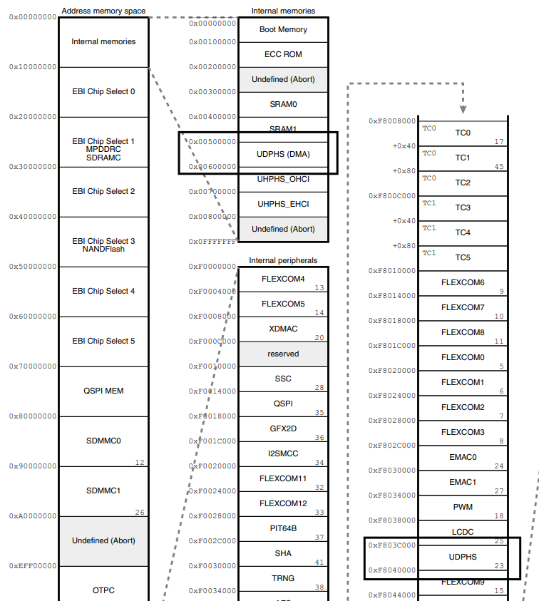
reg=<0x00500000 0x100000 0xf803c000 0x400>;.
In this string, the first pair (0x00500000 0x100000)
specifies the base address and size of the main register space for the USB
gadget controller. The second pair (0xf803c000 0x400)
defines an additional memory region used for Control or Status
registers.
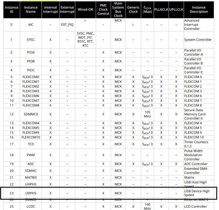
The interrupts property specifies the peripheral ID as listed in the data sheet, followed by the interrupt type (such as level high or low). For a detailed explanation of the mapping, refer to include/dt-bindings/interrupt-controller/irq.h. The interrupt priority can be set from 0 to 7.
The clocks property should be assigned according to the available and compatible options specified in the data sheet. In this case, the assignment follows the order of the clock provider and instance ID. For more information on clock mapping, see include/dt-bindings/clock/at91.h.
The assigned clock property assigns the parent clock to the peripheral clock with a frequency of 480 MHz.
Similarly, the value for each property can be found in the documentation for the Microchip USB driver (Documentation/devicetree/bindings/usb/atmel-usb.txt) within the Linux source code.
- See Appendix 1 for comprehensive documentation on all nodes used in the SAM9X60-Curiosity board.
- See Appendix 2 for comprehensive documentation on the device tree properties.