7.1 PL460-EK Modifications Required for
Compatibility With Revision 5
Users need to make these changes in the PL460-EK revision 4 and earlier versions
to work with the current firmware:
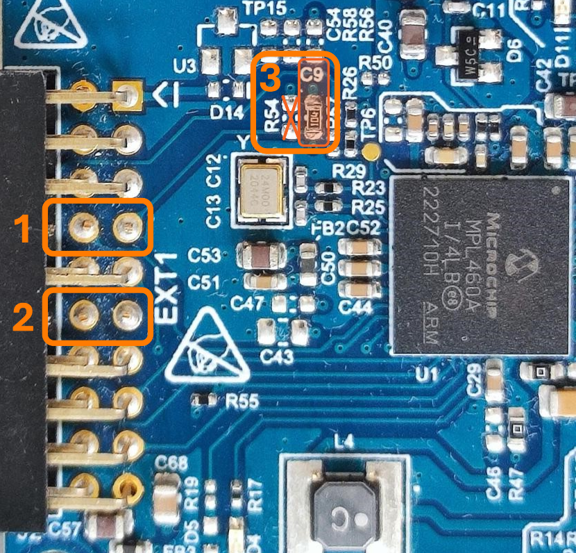
On the top side of the board, users need to make the changes shown in the figure
below:
Cut the "NRST"
and "EN" traces by cutting pin 7 and pin 8 of the
connector J2.
Cut the "STBY"
and "CD" traces by cutting pin 11 and pin 12 of the
connector J2.
Remove the R54
resistor and replace the C9 capacitor with a 10 kΩ resistor
to implement a pull-down on the NRST signal.
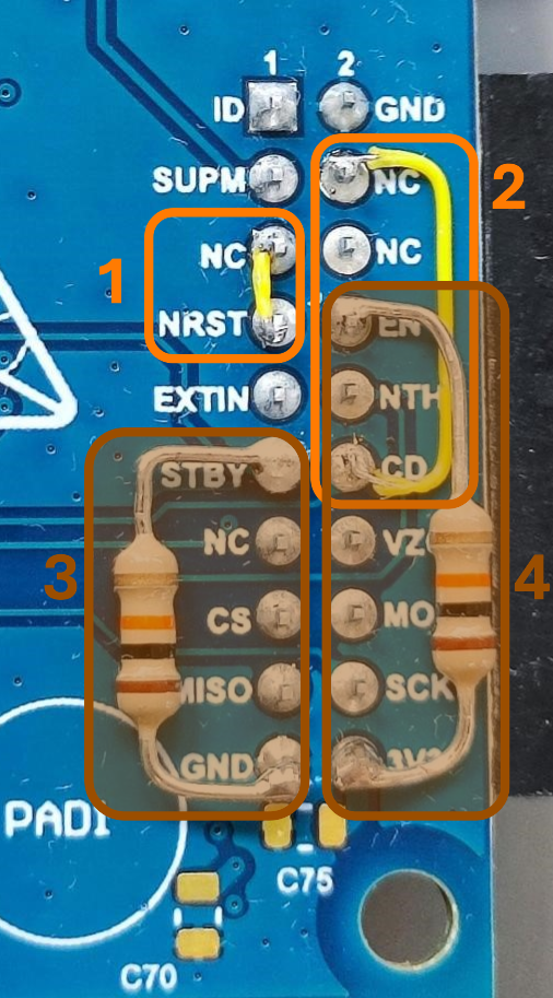
On the bottom side of the board, users need to make the changes shown in the
figure below:
Connect the
"NRST" trace by connecting pin 7 to pin 5 of the connector
J2.
Connect the "CD"
trace by connecting pin 12 to pin 4 of the connector
J2.
Add a 10 kΩ
pull-down resistor to the "STBY" trace by connecting a 10 kΩ
through hole resistor between the pin 11 and the pin 19 of
the connector J2.
Add a 10 kΩ
pull-up resistor to the “EN” trace by connecting a 10 kΩ
through hole resistor between the pin 8 and the pin 20 of
the connector J2.
The operating range of the Supply Monitor has been adjusted to support the
platforms without requiring any modifications. To ensure compatibility with
previous designs, R51 should be replaced with a 120 kΩ 1% resistor.
Table 7-1. Comparison of Xplained
Pro Signals Between Revision 5 and Previous Versions
The XPL_ENABLE
signal is not connected by default. If users need to control
this signal, add resistor R71 (0Ω).
The XPL_STBY
signal is not connected by default. If users need to
control this signal, add resistor R68 (0Ω).
The XPL_VZC
signal is not connected by default. If users need to control
this signal, add resistor R57 (0Ω). See Zero-Crossing Detector Circuit
for additional information.
The online versions of the documents are provided as a courtesy. Verify all content and data in the device’s PDF documentation found on the device product page.