
3.4 Use Case 4: Stereo Single-Ended Audio DAC with Active Low-Pass Filter
The overall response of the suggested filter can be simulated with Mindi using the Datasheet_SE_active_filter.wxsch file, available in the MPLAB® Mindi™ Analog Simulator Software Library (see the Appendix). An extra 22kΩ resistor is added to emulate the input impedance of the receiving equipment, and the DC biasing of the operational amplifier is performed through a resistor pair with a capacitor to ground for noise filtering, as shown in the following figure.
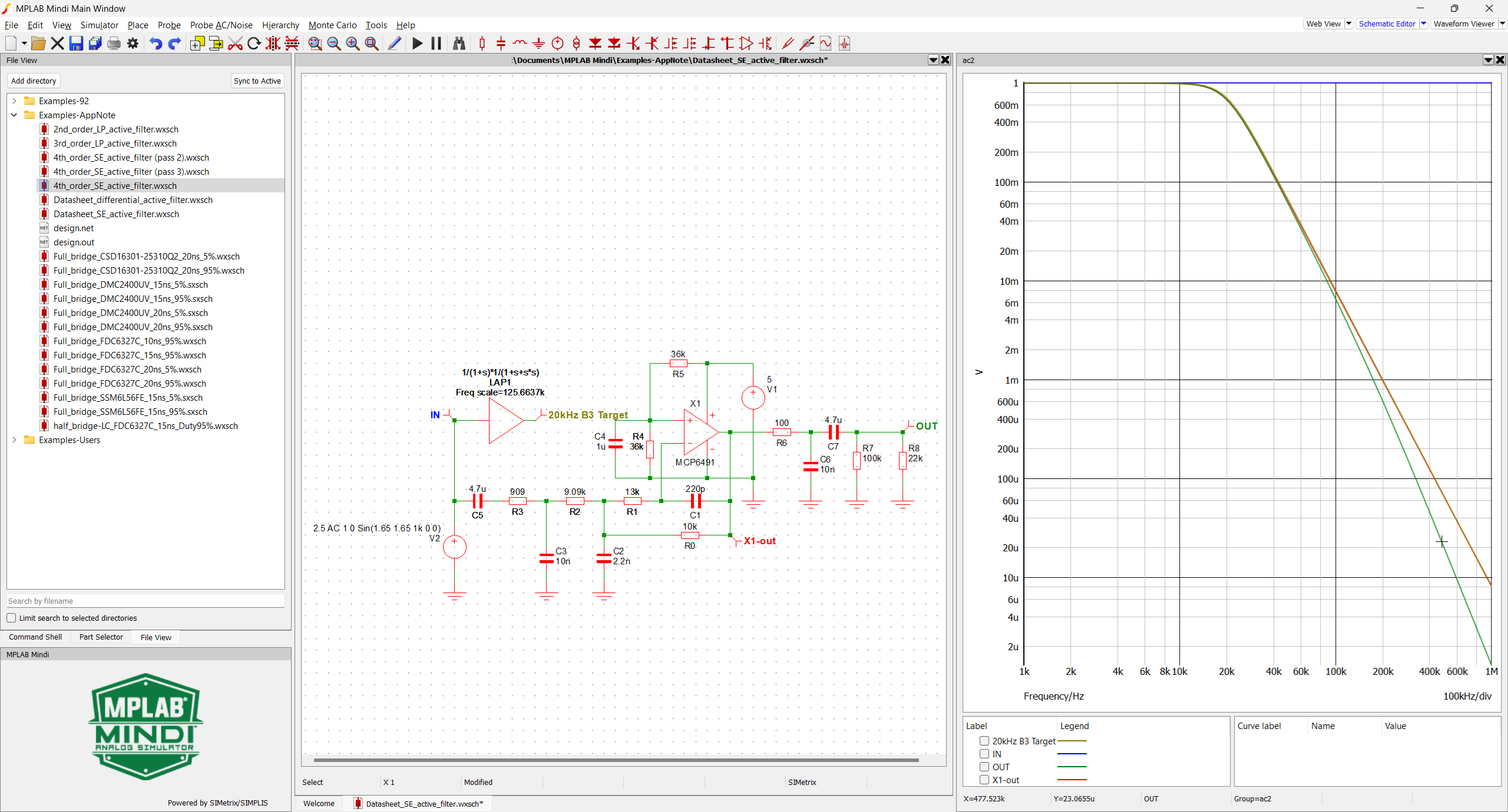
X1-out (green trace) closely matches a 20 kHz third-order Butterworth LP filter (red trace) in the vicinity of the 20 kHz cut-off frequency. R6-C6 then adds an additional first order at 159 kHz.
To enhance this process and allow the user to freely select the low-pass type, corner frequency and gain, a filter calculator is provided, along with the simulation files, in the MPLAB® Mindi™ Analog Simulator Software Library. See the Appendix. This calculator helps compute passive components of single operational amplifier multiple-feedback LP filters up to the fourth order.
Refer to Use Case 4 Output Filter Computation for further details.