
3.3 Use Case 3: Stereo Audio DAC with Active Differential to Single-Ended Low-Pass Filter
The overall response of the suggested filter can be simulated with Mindi™ using the Datasheet_differential_active_filter.wxsch file, available from the MPLAB® Mindi™ Analog Simulator Software Library (see the Appendix). An extra 22kΩ resistor is added to emulate the input impedance of the receiving equipment, and the DC biasing of the operational amplifier is performed through an auxiliary operational amplifier that buffers a resistor pair with a capacitor to ground for noise filtering. This VDD/2 source can be shared between the two channels in a stereo setup, as shown below.
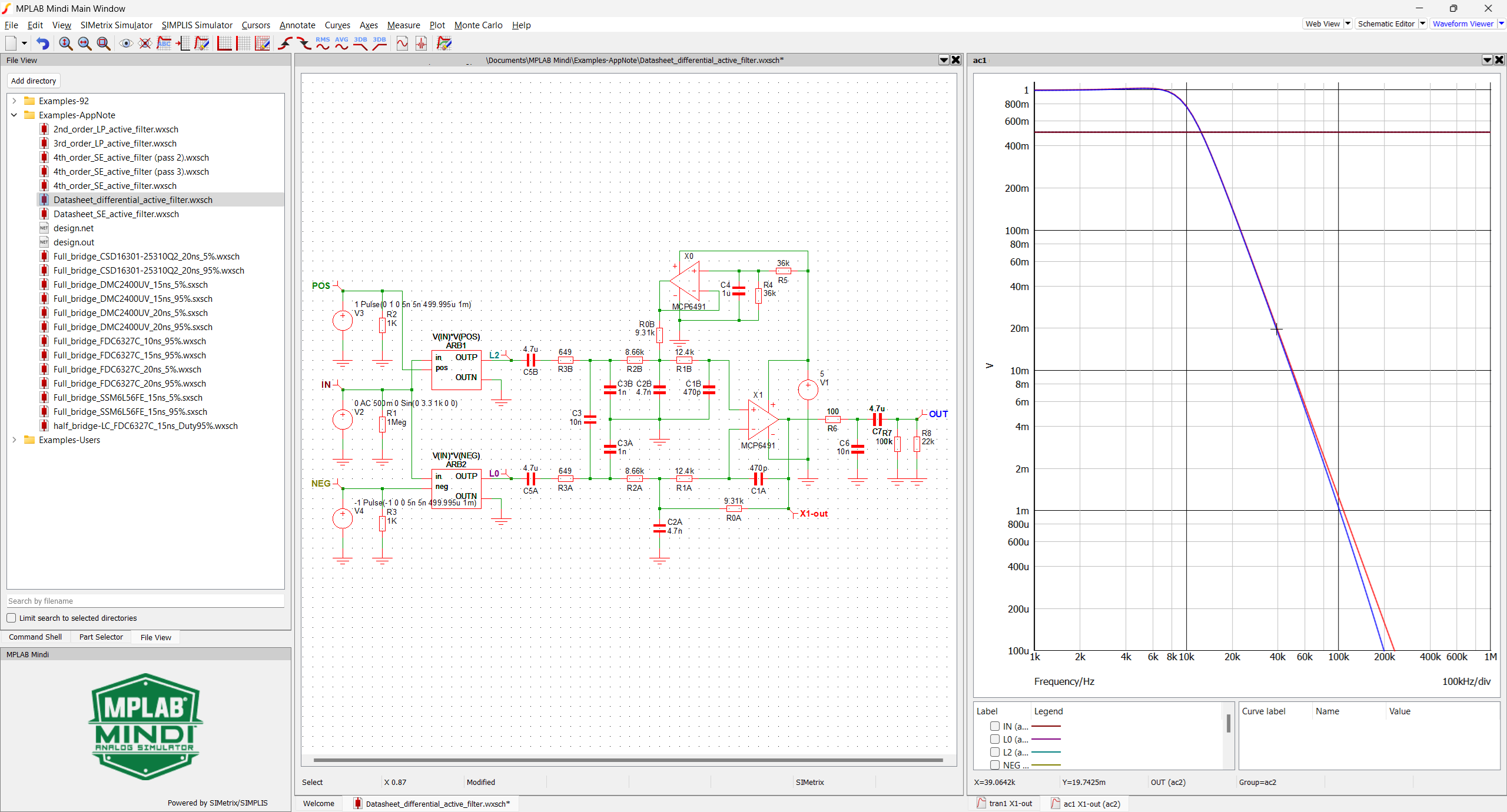
The red trace (X1-out) closely matches a 20 kHz third-order Butterworth low-pass (LP) filter with unity gain (with regard to differential input voltage). R6-C6 adds an additional first order at 159 kHz.
A behavioral model was built to perform a transient analysis, taking into account the half-wave rectification of the input signal, with one digital output handling the positive alternates and the other handling the negative alternates. The model does not include PWM modulation.
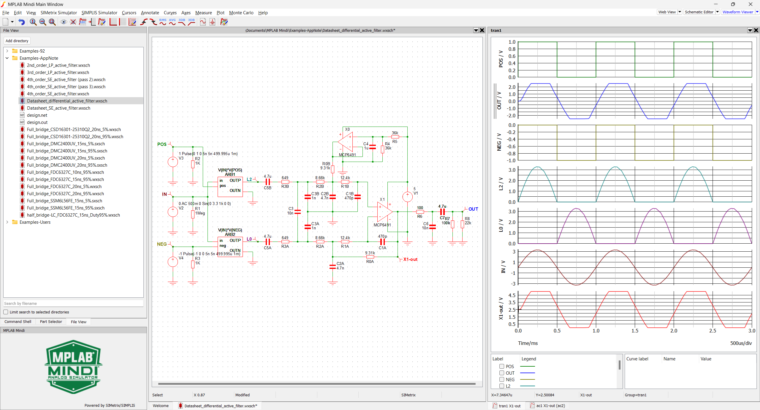
This model shows that the circuit saturates when submitted to full scale 3.3V sinewave arches, which is close to what the PWM output creates. To prevent this, the DAC output level must be limited to a maximum of -4 or -5 dB.
To enhance this process and allow the user to freely select the low-pass type, corner frequency and the gain, a filter calculator up to the fourth order is provided, along with the simulation files in the MPLAB® Mindi™ Analog Simulator Software Library. See the Appendix.
Refer to Use Case 3 Output Filter Computation for further details.