
2.2 Data Visualizer Run Time (DVRT) Library Overview
The MCC Melody Data Visualizer Run Time (DVRT) Library supports the the DVRT functionality of the MPLAB Data Visualizer on a host computer. The DVRT Library allows the user to "watch" and plot project variables at run time on the Data Visualizer plugin window.
2.2.1 MCC Melody Important References
- MCC Melody Technical Reference - Introduction
- MCC Melody Components
- MCC and MCC Melody API References (MCU Families: AVR , PIC16F / PIC18F, dsPIC33)
2.2.2 How to use the Data Visualizer Run Time Library
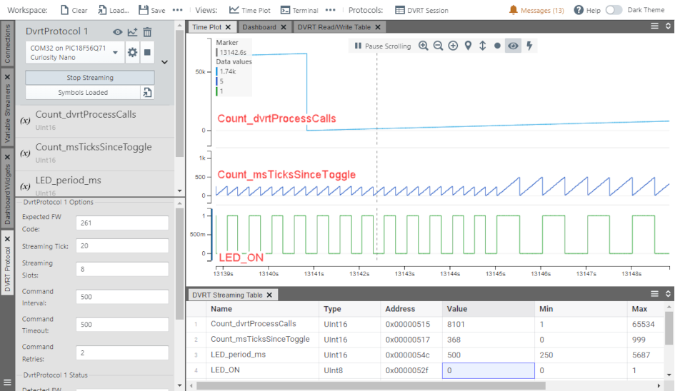
- Count_msTicksSinceToggle is incremented up to toggle_ms, when LED_ON is toggled
- Count_dvrtProcessCalls is incremented before calling the DVRT_process( )
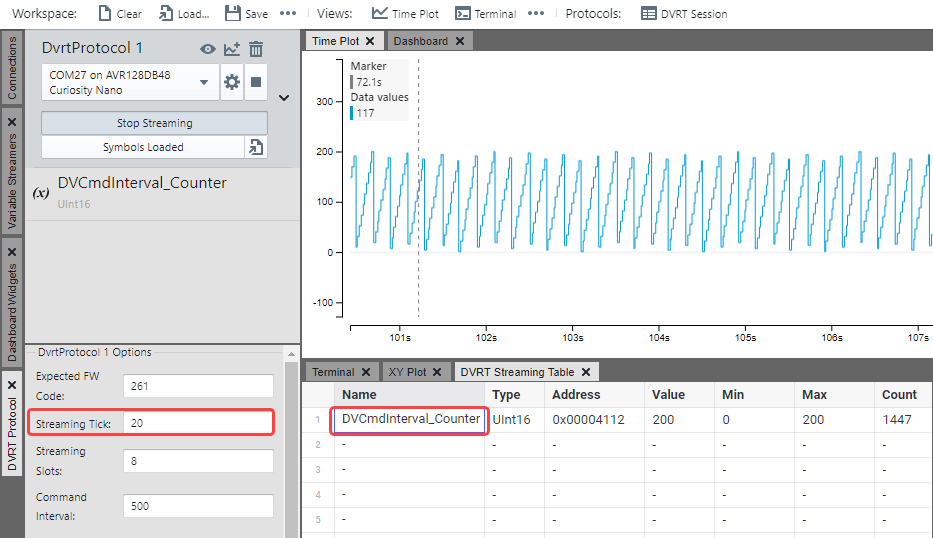
This is the minimum you'll need to add to your own project to use DVRT. The example can be verified by watching the DVCmdInterval_Counter, which is incremented within DVRT_process( ).
 |

Running Use Case 2: 2.2.4.4.1.3 DVRT Minimum Project
2.2.3 Data Visualizer Run Time Basics

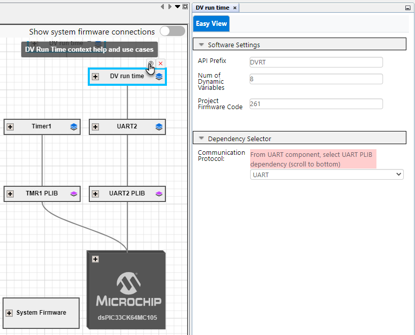
2.2.3.1 MCC Melody DVRT Library Configuration Options
- API Prefix: This text will be the prefix for all API associated with the DVRT.
- Number of Dynamic
Variables: This number should by >= to the number of variables
in the DVRT Streaming Table in the Data Visualizer. On the Data Visualizer side,
this is configured by setting the number of Streaming Slots.
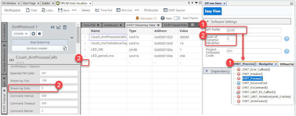
- Project FW Code: Can be
used to distinguish between different projects. The data visualizer compares the
Firmware Code read from the target, to an expected value. A warning is displayed
if the values don't match.
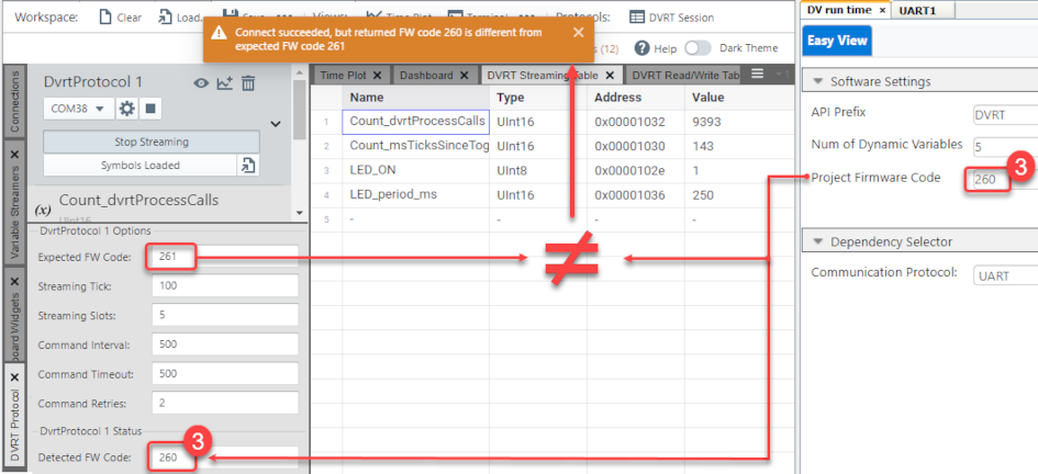 Note: The default value of the Project Firmware Code matches the Expected FM Code in the Data Visualizer.Note: This Project Firmware Code, is used in the DVRunTime_Config.h
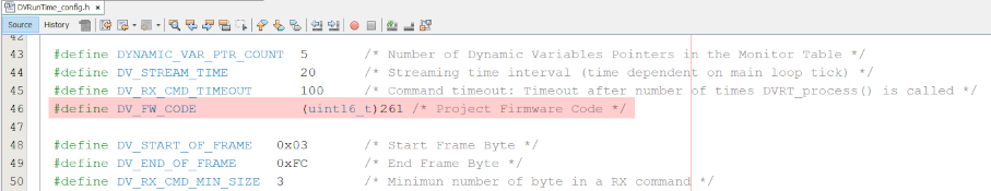
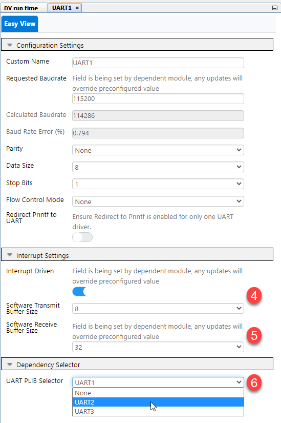
- UART Software Transmit Buffer Size: Only a single byte is used by DVRT, so this can be configured based on user project requirements.
- UART Software Receive Buffer
Size: Receive buffer for DVRT Frame, needs to fit largest command, i.e.
UpdateVariablePtrTableCmd, which is 28 bytes by default, when NumVars = 8. Note: Frame calculation: Start_Byte + Cmd_Byte + NumVars_Byte + (NumVars * 3 Bytes) + End_Byte.
- UART Dependency Selection:
Determine the UART instance connected to your computer's COM port, which
could be a Virtual Serial Port (CDC). Check the board layout schematic on the
MCU side to find the UART instance and the Device Manager for Windows or on a
Mac terminal type
ls /dev/tty.*to find which serial port the UART is connected to.Note: CDC refers to USB Communications Class DeviceNote: For Curiosity Nano boards, this is usually the UART instance connected to the debugger. Using USB-to-Serial bridges should also work. Here the Data Visualizer will automatically detect the COM port of the connected kit.
2.2.3.2 DV Run Time Implementation
Responsibilities: MCU Side and HOST PC Side
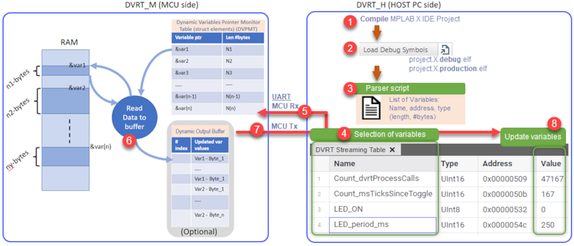
- MPLAB X IDE MCU Project is compiled and an .elf file produced.
- The .elf file is loaded in
the data visualizer.Note: Note you must choose the debug or production version of the .elf, matching your compilation settings.

- A Parser script is used to
generate a list of variables. Note: For volatile variables, this .elf file contains their name, address and type (length in bytes), i.e., at compile time, it is known where volatile variables will be located in the Microcontroller's RAM.
- DVRT Streaming Table is used to select variables of interest to watch at run time.
- As variables are selected,
DVRT command UPDATE_VARIABLE_POINTER_TABLE is sent to the microcontroller to
add these variables to a Dynamic Variables Pointer Monitor Table (DVPMT).
Note: For each variable, this is the address of the variable in the MCU's RAM, and the number of bytes is saved.
- The values of variables are fetched from specific locations in RAM and the Dynamic Output Buffer now contains updated values of each variable in the DVRT Streaming Table.
- Data Output Buffer sent over UART to Data Visualizer.
- Variable values updated in the DVRT Streaming Table.
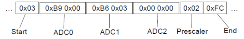
Data Stream Protocol Format
The DV Run Time at the lowest level implements the Data Stream protocol to send data to the Data Visualizer.
The Data Stream Format is processed in the same order as the variables specified in the Variable Streamer. All data must be given as little-endian values, meaning sending the lowest byte first. Additionally, the Data Streamer Protocol requires a start byte and an end byte which are the one's complement (~) of each other. For example, if the startByte is: 0b0000 0011, the endByte will be 0b1111 1100. This wrapper, consisting of one byte before and one byte after the data stream variables, is used by the interpreter to synchronize it to the data stream. The start byte can be arbitrary, but the end byte must be the inverse of the start byte.
2.2.4 DV Run Time API Reference
2.2.4.1 Module Documentation
2.2.4.1.1 DV Run Time
Module description
This file contains the API prototypes for the dvruntime driver module.
Data structures
struct DVRT_interface_t
Structure containing the function pointers to the DV Run Time driver APIs.
Functions
void DVRT_Initialize (void)
Initializes the DVRT driver. Sets the variable values to their initial values and registers error callback functions for UART errors.
void DVRT_Process (void)
Processes the DVRT driver. Checks the UART for incoming data and processes the data if it is available. It also checks for time-out conditions and triggers the periodic sending of data if required. Finally, it executes one-shot readings and ping commands.
Variables
const DVRT_interface_t DVRT
Declaration of the DVRT interface and its function pointers.
Function Documentation
DVRT_Initialize()
void DVRT_Initialize (void )
Initializes the DVRT driver. Sets the variable values to their initial values and registers error callback functions for UART errors.
| None. |
None. |
DVRT_Process()
void DVRT_Process (void )
Processes the DVRT driver. Checks the UART for incoming data and processes the data if it is available. It also checks for time-out conditions and triggers the periodic sending of data if required. Finally, it executes one-shot readings and ping commands.
| None. |
None. |
Variable Documentation
DVRT
const DVRT_interface_t DVRT
Declaration of the DVRT interface and its function pointers.
Section: Included Files Section: Data Type Definitions
2.2.4.2 Class Documentation
2.2.4.2.1 DVCmds Union Reference
Public Attributes
DVRT_StreamUpdates_t stream
DVRT_VariableUpdate_t Var
DVRT_StreamIntervalUpdate_t interval
DVRT_CommandTemplate_t generic
uint8_t DVCmdArray [sizeof(DVRT_StreamUpdates_t)]
Member Data Documentation
DVCmdArray
uint8_t DVCmdArray[sizeof(DVRT_StreamUpdates_t)]
generic
DVRT_CommandTemplate_t generic
interval
DVRT_StreamIntervalUpdate_t interval
stream
DVRT_StreamUpdates_t stream
Var
DVRT_VariableUpdate_t Var
2.2.4.2.2 DVRT_interface_t Struct Reference
Structure containing the function pointers to the DV Run Time driver APIs.
Detailed Description
Structure containing the function pointers to the DV Run Time driver APIs.
Section: Included Files Selecion: Data Type Definitions
#include <DVRunTime_interface.h>
Public Attributes
void(* Initialize )(void)
void(* Process )(void)
Member Data Documentation
The documentation for this struct was generated from the following file:
source/
Initialize
void(* Initialize) (void)
Process
void(* Process) (void)
2.2.4.2.3 flagS Struct Reference
Public Attributes
Member Data Documentation
osr
unsigned osr
ping
unsigned ping
streamOn
unsigned streamOn
2.2.4.3 File Documentation
2.2.4.3.1 source/DVRunTime.c File Reference
This file contains the driver implementation for the dvruntime driver module.
#include "../../DVRT/DVRunTime.h"
#include "../../uart/uart2.h"
Data structures
Functions
void DVRT_UART_RX_CallBack (void)
void DVRT_HandleCommand (void)
void DVRT_UART_WriteByte (uint8_t)
void DVRT_WritePacket (void)
void DVRT_Error_Callback (void)
void DVRT_Initialize (void)
Initializes the DVRT driver. Sets the variable values to their initial values and registers error callback functions for UART errors.
void DVRT_Process ()
Processes the DVRT driver. Checks the UART for incoming data and processes the data if it is available. It also checks for time-out conditions and triggers the periodic sending of data if required. Finally, it executes one-shot readings and ping commands.
Variables
static const uart_drv_interface_t * UART = &UART2
DVRT_error_t error
const DVRT_interface_t DVRT
Declaration of the DVRT interface and its function pointers.
DVRT_VariablePointerTableEntry_t DVPMT [DYNAMIC_VAR_PTR_COUNT]
volatile union DVCmds DVRT_ReceivedCmd
const volatile uint16_t dvIdFw = DV_FW_CODE
volatile uint8_t rxBufPtr
volatile uint8_t tickCounter
uint16_t DVStreamInterval
uint16_t DVStreamInterval_Counter
uint16_t DVCmdInterval
uint16_t DVCmdInterval_Counter
Detailed Description
This file contains the driver implementation for the dvruntime driver module.
dvruntime Generated Driver Source File
Function Documentation
DVRT_Error_Callback()
void DVRT_Error_Callback (void )
DVRT_HandleCommand()
void DVRT_HandleCommand (void )
DVRT_UART_RX_CallBack()
void DVRT_UART_RX_CallBack (void )
Section: Driver Interface
DVRT_UART_WriteByte()
void DVRT_UART_WriteByte (uint8_t txData)
DVRT_WritePacket()
void DVRT_WritePacket (void )
Variable Documentation
DVCmdInterval
uint16_t DVCmdInterval
DVCmdInterval_Counter
uint16_t DVCmdInterval_Counter
DVflag
struct flagS DVflag
dvIdFw
const volatile uint16_t dvIdFw = DV_FW_CODE
DVPMT
DVRT_VariablePointerTableEntry_t DVPMT[DYNAMIC_VAR_PTR_COUNT]
Section: Variables
DVRT_ReceivedCmd
volatile union DVCmds DVRT_ReceivedCmd
DVStreamInterval
uint16_t DVStreamInterval
DVStreamInterval_Counter
uint16_t DVStreamInterval_Counter
error
DVRT_error_t error
rxBufPtr
volatile uint8_t rxBufPtr
tickCounter
volatile uint8_t tickCounter
UART
const uart_drv_interface_t* UART = &UART2[static]
Section: Included Files Section: Macro Declarations
2.2.4.3.2 source/DVRunTime.h File Reference
#include <stdbool.h>
#include <stdint.h>
#include "DVRunTime_interface.h"
#include "DVRunTime_types.h"
#include "DVRunTime_config.h"
Functions
void DVRT_Initialize (void)
Initializes the DVRT driver. Sets the variable values to their initial values and registers error callback functions for UART errors.
void DVRT_Process (void)
Processes the DVRT driver. Checks the UART for incoming data and processes the data if it is available. It also checks for time-out conditions and triggers the periodic sending of data if required. Finally, it executes one-shot readings and ping commands.
Macros
#define EXTERN extern
Variables
const DVRT_interface_t DVRT
Declaration of the DVRT interface and its function pointers.
Detailed Description
dvruntime Generated Driver Header File
Macro Definition Documentation
EXTERN
#define EXTERN extern
2.2.4.3.3 source/DVRunTime_config.h File Reference
This file contains the macros for the configuration of the dvruntime module.
Macros
#define DYNAMIC_VAR_PTR_COUNT 8 /* Number of Dynamic Variables Pointers in the Monitor Table */
#define DV_STREAM_TIME 20 /* Streaming time interval (time dependent on main loop tick) */
#define DV_RX_CMD_TIMEOUT 200 /* Command timeout: Timeout after number of times DVRT_process() is called */
#define DV_FW_CODE (uint16_t)261 /* Project Firmware Code */
#define DV_START_OF_FRAME 0x03 /* Start Frame Byte */
#define DV_END_OF_FRAME 0xFC /* End Frame Byte */
#define DV_RX_CMD_MIN_SIZE 3 /* Minimun number of byte in a RX command */
Detailed Description
This file contains the macros for the configuration of the dvruntime module.
dvruntime Generated Configuration Header File
Macro Definition Documentation
DV_END_OF_FRAME
#define DV_END_OF_FRAME 0xFC /* End Frame Byte */
DV_FW_CODE
#define DV_FW_CODE (uint16_t)261 /* Project Firmware Code */
DV_RX_CMD_MIN_SIZE
#define DV_RX_CMD_MIN_SIZE 3 /* Minimun number of byte in a RX command */
DV_RX_CMD_TIMEOUT
#define DV_RX_CMD_TIMEOUT 200 /* Command timeout: Timeout after number of times DVRT_process() is called */
DV_START_OF_FRAME
#define DV_START_OF_FRAME 0x03 /* Start Frame Byte */
DV_STREAM_TIME
#define DV_STREAM_TIME 20 /* Streaming time interval (time dependent on main loop tick) */
DYNAMIC_VAR_PTR_COUNT
#define DYNAMIC_VAR_PTR_COUNT 8 /* Number of Dynamic Variables Pointers in the Monitor Table */
2.2.4.3.4 source/DVRunTime_interface.h File Reference
Contains the function pointers to the DV Run Time library component.
#include <stdbool.h>
#include <stdint.h>
Data structures
struct DVRT_interface_t
Structure containing the function pointers to the DV Run Time driver APIs.
Detailed Description
Contains the function pointers to the DV Run Time library component.
dvruntime Generated Interface Header File
2.2.4.4 Module Documentation
2.2.4.4.1 DV Run Time Library Use Cases
DV Run Time Library Use Case Code Snippet Instructions
The use cases show example uses of the Data Visualizer Run Time feature, within an MCC Melody Project.
Add the following components and configure them as described in the specific example. Note: Fairly high system clock is required, but this can be lowered once done with the debugging/verification of application functionality with the DVRT.
-
Add DV Run Time.
-
Clock Control:
-
Check that system clock is fast enough, to give a UART baud rate error < 1%
-
-
Pins:
-
Best practice: Enable (weak)pullup on UART Rx pin
-
DVRT Hello World: LED Toggle and Count Variables (Timer)
-
Count_msTicksSinceToggle is incremented up to toggle_ms, when LED_ON is toggled
-
Count_dvrtProcessCalls is incremented before calling the DVRT_Process( )
-
Add DV Run Time.
-
Add a Timer.
-
Dependency Selector
-
Select UART PLIB dependency: Check the schematic for the UART connected to the debugger.
-
-
Hardware Settings:
-
Requested Period(s): 0.001 (s) // 1 ms.
-
-
Interrupt Settings:
-
TMR Interrupt: Yes.
-
-
Pin Grid View:
-
Select a LED pin (check schematic), and configure it as Output.
-
-
Pins:
-
LED pin: Custom name "LED".
-
Best practice: Enable (weak)pullup on UART Rx pin
-
-
Clock Control:
-
Check that system clock is fast enough, to give a UART baud rate error < 1%
-
After configuring the components as described above click Generate to generate the code. Then add the following code snippets to your application:
-
Add the following variables:
-
uint16_t Count_dvrtProcessCalls.
-
uint16_t Count_msTicksSinceToggle.
-
uint16_t LED_period_ms.
-
bool LED_ON.
-
/* Include for PIC16F/18F and AVR*/
#include "mcc_generated_files/system/system.h"
/* Includes for dsPIC and PIC24*/
#include "mcc_generated_files/system/system.h"
#include "mcc_generated_files/system/pins.h"
#include "mcc_generated_files/DVRT/DVRunTime.h"
#include "mcc_generated_files/timer/tmr1.h"   /* Replace with appropriate header from: .../timer/timerX.h */
#include <stdbool.h>
/* Replace with TMR_INTERFACE / TIMER_INTERFACE from: MCC Generated Files/timer/timerX.h */
const struct TMR_INTERFACE *Timer = &Timer0;

volatile bool     LED_ON = false;
volatile uint16_t LED_period_ms = 250;
volatile uint8_t  msTick = 0;
volatile uint16_t Count_msTicksSinceToggle = 0;
volatile uint16_t Count_dvrtProcessCalls = 0;
void Timer_Callback_1ms(void){
    msTick = 1;
    Count_msTicksSinceToggle++;
    if(Count_msTicksSinceToggle >= LED_period_ms){
        LED_ON = !LED_ON;    // Toggle LED state variable
        LED_Toggle();
        Count_msTicksSinceToggle = 0;
    }
}
int main(void)
{
    SYSTEM_Initialize();
    DVRT_Initialize();
    Timer->TimeoutCallbackRegister(Timer_Callback_1ms);

    INTERRUPT_GlobalInterruptEnable();
    //For Q71 INTERRUPT_GlobalInterruptHighEnable();
    //For AVR: Enable Global IRQ in Interrupt Manager
    //For dsPIC, Global IRQs are enabled by default

    while(1){
        if(msTick == 1){
            msTick = 0;
            Count_dvrtProcessCalls++;
            DVRT_Process();
        }
    }
}
DVRT Minimum Project
This is the minimum you'll need to add to your own project to use DVRT. The example can be verified by watching the DVCmdInterval_Counter, which is incremented within DVRT_process().
-
Add DV Run Time.
-
Add a Timer.
-
Dependency Selector
-
Select UART PLIB dependency: Check the schematic for the UART connected to the debugger.
-
-
Hardware Settings:
-
Requested Period(s): 0.001 (s) // 1 ms.
-
-
Interrupt Settings:
-
TMR Interrupt: No.
-
-
Clock Control:
-
Check that system clock is fast enough, to give a UART baud rate error < 1%
-
-
Pins:
-
Best practice: Enable (weak)pullup on UART Rx pin
-
After configuring the components as described above click Generate to generate the code. Then add the following code snippets to your application:
-
Add the following variables:
-
DVCmdInterval_Counter
Hint: Search for "count"
-
/* DVRT minimum project: dsPIC, PIC24 */
#include "mcc_generated_files/system/system.h"
#include "mcc_generated_files/DVRT/DVRunTime.h"
#include "mcc_generated_files/timer/tmr1.h"   /* Replace with appropriate header from: .../timer/timerX.h */

/* Replace with TMR_INTERFACE / TIMER_INTERFACE from: MCC Generated Files/timer/timerX.h */
const struct TIMER_INTERFACE *Timer = &Timer1;

int main(void)
{
    SYSTEM_Initialize();
    DVRT_Initialize();
    Timer->TimeoutCallbackRegister(DVRT_Process);

    while(1){
        Timer->Tasks();
    }
}
/* DVRT minimum project for PIC16F/18F, coming soon for AVR */
#include "mcc_generated_files/system/system.h"
/* Replace with TMR_INTERFACE / TIMER_INTERFACE from: MCC Generated Files/timer/timerX.h */
const struct TMR_INTERFACE *Timer = &tmr0;

int main(void)
{
    SYSTEM_Initialize();
    DVRT_Initialize();
    Timer->TimeoutCallbackRegister(DVRT_Process);

    INTERRUPT_GlobalInterruptEnable();
    /*For Q71: INTERRUPT_GlobalInterruptHighEnable(); */

    while(1){
        Timer->Tasks();
    }
}