
2.1 Data Streamer Library Overview
2.1.1 How to use the Data Streamer
- 2.1.3.7.2 Data Streamer Use Case 1: Continuously Sending Frames This example shows the application code needed to send the variables shown in the Data Streamer Basics section.
- 2.1.3.7.3 Data Streamer Use Case 2: Using a Custom Structure to Send a FrameThe custom struct for the Data Streamer, allows you to very easily change the variables that you are interested in plotting. This project achieves the same as the first, just showing the refactoring needed to use the custom struct.
- 2.1.3.7.4 Data Streamer Use Case 3: Send Frames at a Period Set by the TimerShows how to use a timer overflow callback to set the frequency of Data Streamer frames sent to the Data Visualizer. The Global variable SEND_FRAME is defined created as volatile to prevent the compiler optimizing it away, since changed asynchronously by an interrupt/callback.
 |
 |
 |
- Recommended starting point: UART Driver, Timer/Counter A PLIB Driver and the Data Streamer Library.
- Videos also included for: RTC PLIB Driver, ADC PLIB Driver, AVR Event System.
- Recommended starting point: UART Driver, Timer0 PLIB Driver and the Data Streamer Library.
- Videos also included for: ADCC PLIB Driver.
2.1.2 Data Streamer Basics
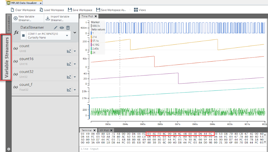
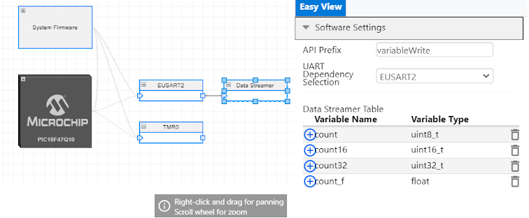
The MPLAB Data Visualizer can directly plot 8-bit hex values, received from an embedded application. Variable Streamers are supported by the MPLAB Data Visualizer, to display these variables on a graph (or custom dashboard). To do this such as the embedded application must send these variables using the Stream Format (found in Variable Streamers), a light-weight framing format to pack several numerical values over one interface. .
The Data Streamer Library is a simple driver which implements the Data Streamer Protocol.
The example above was generated using the following configuration:
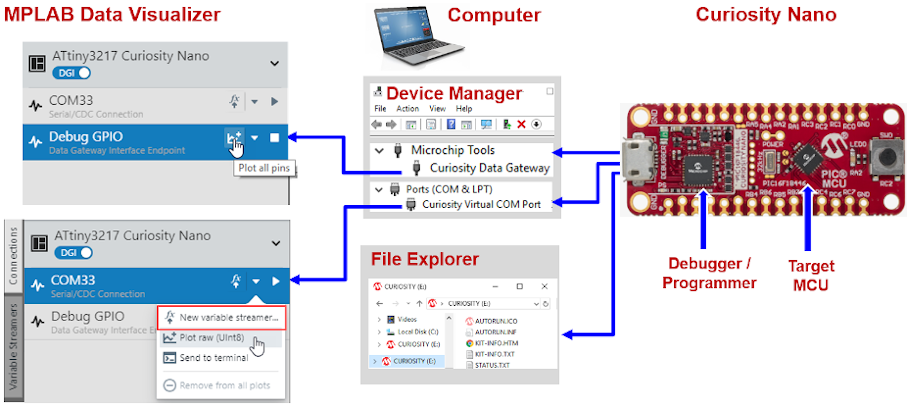
The Data Visualizer can receive data from your embedded target over the following interfaces:
- COM Port (USB CDC) in which case you will typically send data over a UART
- Data Gateway Interface, which supports UART, SPI or I2C communication.
Version 1 of the Data Streamer supports only the COM Port interface, over UART.
2.1.3 Data Streamer Implementation
Data Stream Protocol Format
The Data Stream Format is processed in the same order as the variables specified in the Variable Streamer. All data must be given as little endian values, meaning that the lowest byte must be sent first.
Additionally, the Data Streamer Protocol requires a start byte and end byte which are the one's compliment (~) of each other. For example if the startByte is: 0b0000 0011, the endByte will be: 0b1111 1100. This wrapper, consisting of one byte before and one byte after the data stream variables, is used by the interpreter to synchronize it to the data stream. The start byte can be arbitrary but the end byte must be the inverse of the start byte.
The figure below gives an example of a raw data transmission where ADC0 is 185, ADC1 is 950, ADC2 is 0, and Prescaler is 2.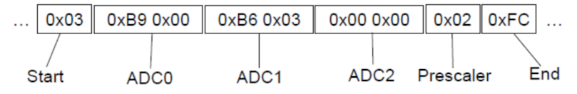
2.1.3.1 Data Stream File Configuration Format (.ds)
The configuration file is a comma-delimited text file that specifies one data variable per line. Each line starts by specifying the data format of the variable by one of the tags presented in the table below. The position of the variable in the output grid is then given by two coordinates starting at index 1. The fourth parameter assigns a text string to the variable, followed by two optional parameters: the first is Display Format and the second is a formula to convert the input data. The formula is applied on the input data, and the result will be shown in the format defined by the Display Format. All Data Stream types except the Grid formats are available as Display Format. The two optional parameters are available for all Data Stream types except the Grid types.
| Type | Size | Tag | Example |
|---|---|---|---|
| Unsigned byte | 1 | B | B,1,1,Light,F,variable*2 |
| Signed byte | 1 | -B | -B,1,1,Encoder |
| Unsigned short | 2 | D | D,1,1,ADC |
| Signed short | 2 | -D | -D,1,1,ADC |
| Unsigned word | 4 | W | W,1,1,Transfer rate |
| Signed word | 4 | -W | -W,1,1,Status code |
| Floating point | 4 | F | F,1,1,Temperature |
| Double-precision floating point | 8 | DF | DF,1,1,Measurement |
This is an example configuration:
                D,1,1,ADC0
                D,1,2,ADC1
                D,1,3,ADC2
                B,2,1,Prescaler
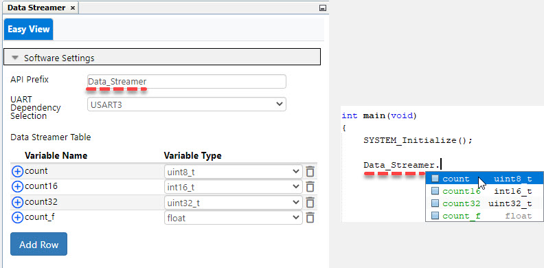
2.1.3.2 Implementation: Data Streamer version >=V1.3
- Variables defined by the user are now stored in a struct:
- Users can also generate their own struct in the main.c file, using Data_Streamer_PackageSet( )
- Users are now no longer required to include the data_streamer.h file in the main.c.
Data Streamer Struct
//data_streamer.c
struct DATA_STREAMER_STRUCT Data_Streamer;
//data_streamer.h
struct DATA_STREAMER_STRUCT
{
    uint8_t count;
    int16_t count16;
    uint32_t count32;
    float count_f;
};//Macro that represents the byte that is sent to signify the beginning of the data streamer frame. #define DATA_STREAMER_START_BYTE 3 //Macro that represents the byte that is sent to signify the end of the data streamer frame. #define DATA_STREAMER_END_BYTE (255 - DATA_STREAMER_START_BYTE)
Between the start and end bytes, the variables should be sent from the application in the same order that they are expected by the MPLAB Data Visualizer.
void Data_Streamer_FrameSend(void *package, size_t length)
{
    Data_Streamer_VariableWrite(DATA_STREAMER_START_BYTE);

    char *dp = package;
    while (length--)
    {
        Data_Streamer_VariableWrite(*dp++);
    }

    Data_Streamer_VariableWrite(DATA_STREAMER_END_BYTE);
    while (!(DATA_STREAMER.IsTxDone()));
};
Each variable is in turn sent using For multi-byte variable types, the bytes
are sent from from least significant to most
significant.static void Data_Streamer_VariableWrite(char var)
{
while (!(DATA_STREAMER.IsTxReady()));
DATA_STREAMER.Write(var);
};2.1.3.3 Implementation: Data Streamer version <=V1.2
#include "../data_streamer/data_streamer.h"
Note: If using MCC-generated GPIO operations and macros within the callbacks, make sure to include pin_manager.h (i.e. #include "../include/pin_manager.h") If using interrupt-driven timers, make sure global interrupts are enabled.
#define DATA_STREAMER_START_BYTE 3  //trivial Data Streamer Protocol start of frame token
#define DATA_STREAMER_END_BYTE (255 - DATA_STREAMER_START_BYTE)
Between the start and end bytes, the variables need to be sent from the application in the same order that they are expected by the MPLAB Data Visualizer.
void variableWrite_sendFrame(uint8_t count, uint16_t count16, uint32_t count32, float count_f)
{
   EUSART2_Write(DATA_STREAMER_START_BYTE);

   EUSART2_Write(count);                /*uint8_t */
   variableWrite_sendValue((uint8_t *) &count16, 2);
   variableWrite_sendValue((uint8_t *) &count32, 4);
   variableWrite_sendValue((uint8_t *) &count_f, 4);

   EUSART2_Write(DATA_STREAMER_END_BYTE);
   while(!EUSART2_IsTxDone());
}
For multi-byte variable types, the bytes are sent from the least significant to the most significant.
static void variableWrite_sendValue(uint8_t* byte_ptr, uint8_t num_bytes)
 {
      for(uint8_t i = 0; i < num_bytes; i++)
      {
         EUSART2_Write(byte_ptr[i]);
      }
}
2.1.3.3.1 GitHub Examples
The following examples show the use of the Data Streamer library using the version 1.2.


2.1.3.4 Module Documentation
2.1.3.4.1 DATASTREAMER
This file contains the API prototypes and the related data structures for the Data Streamer driver.
Module description
This file contains the API prototypes and the related data structures for the Data Streamer driver.
Data structures
struct DATA_STREAMER_STRUCT
Structure containing the initial Data Streamer variables.
struct PACKAGE_STRUCT
Structure containing a pointer assigned to a custom data package and its size which are set by the user.
struct DataStreamer
An instance of the DATA_STREAMER_STRUCT.
struct DATA_STREAMER_PACKAGE
An instance of the PACKAGE_STRUCT.
struct data_streamer_interface_t
Structure containing the function pointers to the Data Streamer communications APIs.
struct DATA_STREAMER
Abstraction interface for the UART peripheral.
Functions
void DataStreamer_Initialize (void)
Initializes the Data Streamer.
void DataStreamer_FrameSend (void *package, size_t length)
Writes the frame to the Data Streamer.
void DataStreamer_PackageSet (void *customStructHandler, size_t customlength)
Sets the package containing the variables to be sent by the Data Streamer.
Function Documentation
DataStreamer_FrameSend()
void DataStreamer_FrameSend (void * package, size_t length)
Writes the frame to the Data Streamer.
| void |
* package - Pointer to the DATA_STREAMER_PACKAGE structure containing the variables to be sent. |
| size_t |
length - Size of the DATA_STREAMER_PACKAGE structure in bytes. |
None. |
DataStreamer_Initialize()
void DataStreamer_Initialize (void )
Initializes the Data Streamer.
| None. |
None. |
DataStreamer_PackageSet()
void DataStreamer_PackageSet (void * customStructHandler, size_t customlength)
Sets the package containing the variables to be sent by the Data Streamer.
| void |
* customStructHandler - Pointer to the user-defined structure containing the variables to be sent to the Data Streamer. |
| size_t |
customlength - Size of the user-defined structure in bytes. |
None. |
2.1.3.5 Class Documentation
2.1.3.5.1 DATA_STREAMER Struct Reference
Abstraction interface for the UART peripheral.
Detailed Description
Abstraction interface for the UART peripheral.
#include <data_streamer_interface.h>
The documentation for this struct was generated from the following file:
source/
2.1.3.5.2 data_streamer_interface_t Struct Reference
Structure containing the function pointers to the Data Streamer communications APIs.
Detailed Description
Structure containing the function pointers to the Data Streamer communications APIs.
#include <data_streamer_interface.h>
Public Attributes
Member Data Documentation
The documentation for this struct was generated from the following file:
source/
IsTxDone
bool(* IsTxDone) (void)
IsTxReady
bool(* IsTxReady) (void)
Write
void(* Write) (uint8_t)
2.1.3.5.3 DATA_STREAMER_PACKAGE Struct Reference
An instance of the PACKAGE_STRUCT.
Detailed Description
An instance of the PACKAGE_STRUCT.
#include <data_streamer.h>
The documentation for this struct was generated from the following file:
source/
2.1.3.5.4 DATA_STREAMER_STRUCT Struct Reference
Structure containing the initial Data Streamer variables.
Detailed Description
Structure containing the initial Data Streamer variables.
#include <data_streamer.h>
Public Attributes
uint8_t varName
Member Data Documentation
varName
uint8_t varName
2.1.3.5.5 DataStreamer Struct Reference
An instance of the DATA_STREAMER_STRUCT.
Detailed Description
An instance of the DATA_STREAMER_STRUCT.
#include <data_streamer.h>
The documentation for this struct was generated from the following file:
source/
2.1.3.5.6 PACKAGE_STRUCT Struct Reference
Structure containing a pointer assigned to a custom data package and its size which are set by the user.
Detailed Description
Structure containing a pointer assigned to a custom data package and its size which are set by the user.
#include <data_streamer.h>
Public Attributes
Member Data Documentation
length
size_t length
varStruct
void* varStruct
2.1.3.6 File Documentation
2.1.3.6.1 source/data_streamer.c File Reference
This file contains the implementation for the Data Streamer driver APIs.
#include "../data_streamer.h"
#include "../data_streamer_interface.h"
Functions
void DataStreamer_Initialize (void)
Initializes the Data Streamer.
static void DataStreamer_VariableWrite (char var)
void DataStreamer_FrameSend (void *package, size_t length)
Writes the frame to the Data Streamer.
void DataStreamer_PackageSet (void *customStructHandler, size_t customlength)
Sets the package containing the variables to be sent by the Data Streamer.
Variables
struct DATA_STREAMER_STRUCT DataStreamer
Detailed Description
This file contains the implementation for the Data Streamer driver APIs.
DATASTREAMER Generated Driver API Source File.
Function Documentation
DataStreamer_VariableWrite()
static void DataStreamer_VariableWrite (char var)[static]
Variable Documentation
DATA_STREAMER_PACKAGE
struct PACKAGE_STRUCT DATA_STREAMER_PACKAGE
DataStreamer
struct DATA_STREAMER_STRUCT DataStreamer
2.1.3.6.2 source/data_streamer.h File Reference
#include "data_streamer_interface.h"
#include <stdio.h>
Data structures
struct DATA_STREAMER_STRUCT
Structure containing the initial Data Streamer variables.
struct PACKAGE_STRUCT
Structure containing a pointer assigned to a custom data package and its size which are set by the user.
Functions
void DataStreamer_Initialize (void)
Initializes the Data Streamer.
void DataStreamer_FrameSend (void *package, size_t length)
Writes the frame to the Data Streamer.
void DataStreamer_PackageSet (void *customStructHandler, size_t customlength)
Sets the package containing the variables to be sent by the Data Streamer.
Macros
#define DATA_STREAMER_START_BYTE 3
#define DATA_STREAMER_END_BYTE (255 - DATA_STREAMER_START_BYTE)
#define WriteFrame() DataStreamer_FrameSend(DATA_STREAMER_PACKAGE.varStruct,DATA_STREAMER_PACKAGE.length);
Variables
struct DATA_STREAMER_STRUCT DataStreamer
Detailed Description
DATASTREAMER Generated Driver API Header File.
Macro Definition Documentation
DATA_STREAMER_END_BYTE
#define DATA_STREAMER_END_BYTE (255 - DATA_STREAMER_START_BYTE)
DATA_STREAMER_START_BYTE
#define DATA_STREAMER_START_BYTE 3
WriteFrame
#define WriteFrame( ) DataStreamer_FrameSend(DATA_STREAMER_PACKAGE.varStruct,DATA_STREAMER_PACKAGE.length);
Variable Documentation
DATA_STREAMER_PACKAGE
struct PACKAGE_STRUCT DATA_STREAMER_PACKAGE
DataStreamer
struct DATA_STREAMER_STRUCT DataStreamer
2.1.3.6.3 source/data_streamer_interface.c File Reference
This contains the implementation of the interface contract between the Data Streamer driver and the selected UART instance.
#include "../data_streamer_interface.h"
#include "../../uart/uart1.h"
Variables
Detailed Description
This contains the implementation of the interface contract between the Data Streamer driver and the selected UART instance.
DATASTREAMER Generated Driver Interface Source API File.
Variable Documentation
DATA_STREAMER
const data_streamer_interface_t DATA_STREAMER
Initial value:
= {
    .Write = &UART1_Write,
    .IsTxReady = &UART1_IsTxReady,
    .IsTxDone = &UART1_IsTxDone,
}
2.1.3.6.4 source/data_streamer_interface.h File Reference
This declares the interface contract between the Data Streamer driver and the selected UART peripheral.
#include <stdbool.h>
#include <stdint.h>
Data structures
struct data_streamer_interface_t
Structure containing the function pointers to the Data Streamer communications APIs.
Variables
Detailed Description
This declares the interface contract between the Data Streamer driver and the selected UART peripheral.
DATASTREAMER Generated Driver Interface API Header File.
Variable Documentation
DATA_STREAMER
const data_streamer_interface_t DATA_STREAMER
2.1.3.7 Data Streamer Use Cases
2.1.3.7.1 Data Streamer Use Case Code Snippet Instructions
-
Add the Data Streamer to the project (Libraries > Data Visualizer > Data Streamer)
-
Check the schematics of the board to see the UART that is connected to the debugger, which has a COM PORT that the PC/Data Visualizer can see
-
Configure the Data Streamer as described in the example
-
Check the Tx/Rx pin configurations in Pin Manager (LED pin where applicable)
-
Generate the code
-
Add the code snippet to the application code (adding the required headers and calling relevant code snippet(s))
-
Program the board
-
Open a terminal (e.g. MPLAB Data Visualizer) and connect at configured baud rate
2.1.3.7.2 Data Streamer Use Case 1: Continuously Sending Frames
This is the simplest implementation. Update the variables, send a frame, then make a LED blink. A delay could easily be added if required, or see use case 3 for a timer implementation.
-
Data Streamer:
-
UART Dependency Selection: Select the UART that is connected to the debugger, which in turn has a COM PORT that PC/Data Visualizer can see (Check the schematics of your board).
-
-
Data Streamer Table: Create the following variables, with the specified types:
-
Count, uint8_t
-
Count16, uint16_t
-
Count32, uint32_t
-
Count_f, float
-
-
System > Pins:
-
Pin Grid View: Select LED pin as output (Check the schematic for your board).
-
Pins: Rename Custom Name to "LED".
-
After configuring the components as described above, click 'Generate' to generate the code. Then add the following code snippets to your application:
#include "mcc_generated_files/system/system.h"

volatile bool SEND_FRAME = false;
//Include delay header if needed.
void DS_Frame_Update(void){
    DataStreamer.count +=5; /*Update variable values */
    DataStreamer.count16 += 1000;
    DataStreamer.count32 += 50000000;
    DataStreamer.count_f += 1.5;
    SEND_FRAME = true;   /* Variable values updated, a new Data Streamer frame can be sent. */
}
int main(void)
{
    SYSTEM_Initialize();

    DataStreamer.count = 0;
    DataStreamer.count16 = 0;
    DataStreamer.count32 = 0;
    DataStreamer.count_f = 1.5;

    while(1)
    {
        DS_Frame_Update();
        if(SEND_FRAME){
            WriteFrame();
            SEND_FRAME = false;
            LED_Toggle();
        }
        // add delay here if needed
    }
}
2.1.3.7.3 Data Streamer Use Case 2: Using a Custom Structure to Send a Frame
The custom structure for the Data Streamer can be used to change the variables. This project shows the refactoring needed to use the custom structure.
This is useful because in the initial stages of an MCC project development the changes of the various MCU peripherals are often done while having the MCC open. However, the final touches can be done without opening the MCC.
Note: The data_streamer.ds file needs to be modified manually.
-
Data Streamer:
-
UART Dependency Selection: Select the UART that is connected to the debugger, which in turn has a COM PORT that PC/Data Visualizer can see (Check the schematics of your board)
-
-
Data Streamer Table: Create the following variables, with the specified types:
-
Count, uint8_t
-
Count16, uint16_t
-
Count32, uint32_t
-
Count_f, float
-
-
System > Pins:
-
Pin Grid View: Select LED pin as output (Check the schematic for your board).
-
Pins: Rename Custom Name to "LED".
-
-
data_streamer.ds file
-
Double click to open: ./mcc_generated_files/data_streamer/data_streamer.ds.
-
Add: W,1,1,new32 (after count32 variable, as shown in the code snippet below).
-
After configuring the components as described above, click 'Generate' to generate the code. Then add the following code snippets to your application:
/* mcc_generated_files/data_streamer/data_streamer.ds */
B,1,1,count
-D,1,1,count16
W,1,1,count32
W,1,1,new32   /* This line is added manually */
F,1,1,count_f
#include "mcc_generated_files/system/system.h"

volatile bool SEND_FRAME = false;

struct{
    uint8_t count;
    uint16_t count16;
    uint32_t count32;
    uint32_t new32;
    float count_f;
}my_struct;
void DS_Frame_Update(void){
    my_struct.count +=5; /*Update variable values */
    my_struct.count16 += 1000;
    my_struct.count32 += 50000000;
    my_struct.new32 += 30000000;
    my_struct.count_f += 1.5;
    SEND_FRAME = true;  /* Variable values updated, a new Data Streamer frame can be sent. */
}
int main(void)
{
    SYSTEM_Initialize();
    DataStreamer_PackageSet(&my_struct,sizeof(my_struct));

    my_struct.count = 0;
    my_struct.count16 = 0;
    my_struct.count32 = 0;
    my_struct.new32 = 0;
    my_struct.count_f = 1.5;

    while(1)
    {
        DS_Frame_Update();
        if(SEND_FRAME){
            WriteFrame();
            SEND_FRAME = false;
            LED_Toggle();
        }
        // add delay here if needed
    }
}
2.1.3.7.4 Data Streamer Use Case 3: Send Frames at a Period Set by the Timer
Shows how to use a timer overflow callback to set the frequency of the Data Streamer frames sent to the Data Visualizer. The Global variable SEND_FRAME is defined as volatile to prevent the compiler optimizing it away, since it can be changed asynchronously.
This is useful because the UART transmissions take a relatively long time, compared to many other MCU tasks, such as getting an ADC result. Thus, moving the processing of longer tasks to the main application reduces the possibility of having interrupts interrupting each other (and the complexity of handling this safely). Simply setting a flag (SEND_FRAME) keeps the associated callback or the Interrupt Services Routine (ISR) short.
-
Data Streamer:
-
UART Dependency Selection: Select the UART that is connected to the debugger, which in turn has a COM PORT that PC/Data Visualizer can see (Check the schematics of your board).
-
-
Data Streamer Table: Create the following variables, with the specified types:
-
Count, uint8_t
-
Count16, uint16_t
-
Count32, uint32_t
-
Count_f, float
-
-
System > Pins:
-
Pin Grid View: Select LED pin as output (Check the schematic for your board).
-
Pins: Rename Custom Name to "LED".
-
-
Timer:
-
Add a timer to your project, follow instructions for 100 ms timer, configure it as directed.
-
After configuring the components as described above, click 'Generate' to generate the code. Then add the following code snippets to your application:
#include "mcc_generated_files/system/system.h"

/* Create a pointer of type TMR_INTERFACE and assign it to the address of the TCA0_Interface TMR_INTERFACE struct.
Add a Timer to your project, look for: const struct TMR_INTERFACE TMRx_xxx in TMRx.c. */
const struct TMR_INTERFACE *Timer = &TCA0_Interface;

volatile bool SEND_FRAME = false;
void Timer_Callback(void){
    LED_Toggle();
    DataStreamer.count +=5; /*Update variable values */
    DataStreamer.count16 += 1000;
    DataStreamer.count32 += 50000000;
    DataStreamer.bobs32 += 30000000;
    DataStreamer.count_f += 1.5;
    SEND_FRAME = true;  /* Variable values updated, a new Data Streamer frame can be sent. */
}
int main(void)
{
    SYSTEM_Initialize();
    Timer->TimeoutCallbackRegister(Timer_Callback);

    DataStreamer.count = 0;
    DataStreamer.count16 = 0;
    DataStreamer.count32 = 0;
    DataStreamer.count_f = 1.5;

    while(1)
    {
        if(SEND_FRAME){
            WriteFrame();
            SEND_FRAME = false;
            LED_Toggle();
        }
    }
}