
3.2 Bench Test Results
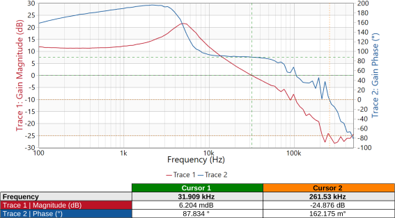
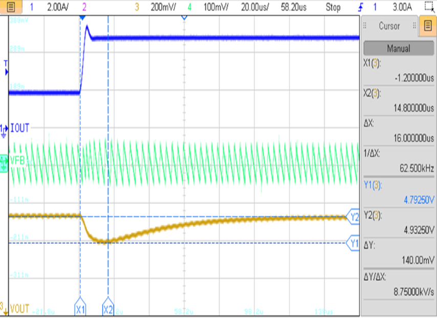
Figure 2-2 shows the implemented test schematics along with the selected ripple injection component values and feedback resistors. The simplified design approach is validated through frequency-domain and transient measurements, as shown in Figure 2-3.
 |  |
| Ripple Injection Components | ΔVFB | FC | Phase Margin | Undershoot | Response Time | Settling Time |
|---|---|---|---|---|---|---|
| CINJ = 100 nF, RINJ = 36k, CFF = 4.7 nF | 108 mV | 31 kHz | 87° | 140 mV | 16 us | 80 us |
The Bode plot indicates a crossover frequency of approximately 31 kHz, which is slightly higher than the earlier frequency-domain design, and a phase margin of about 87°, indicating a highly stable and well-damped control loop. The higher phase margin is a direct result of the larger CFF value used in this approach, which shifts the second zero to a lower frequency and provides stronger phase boost around the crossover region. The measured feedback ripple ΔVFB is approximately 108 mV, which falls within the recommended design range and confirms proper ripple injection.
The transient response further validates the design, with a load step from 2.5A to 5A showing an undershoot of approximately 140 mV, a response time of around 16 µs, and a settling time of about 80 µs. Compared to the optimized frequency-domain design, the transient response is slightly slower, which is expected due to the higher phase margin. This demonstrates the inherent trade-off in control loop design: while the simplified approach provides robust stability and ease of implementation, it may result in reduced transient speed. Overall, the results confirm that the simplified method offers a practical and reliable starting point for ACOT control loop design, especially when rapid design iteration is required.