
2.3 Bench Test Results
While frequency-domain analysis and theoretical calculations provide a strong foundation for ACOT control loop design, it is essential to validate the design through bench measurements. Practical implementations are influenced by parasitic, component tolerances, layout effects, and non-idealities that are not fully captured in analytical models. Therefore, bench testing is critical to confirm that the designed loop achieves the intended crossover frequency, phase margin, and transient performance under real operating conditions. Figure 2-2 shows the implemented test schematics along with the selected ripple injection component values and feedback resistors.
 |  |
| Ripple Injection Components | ΔVFB | FC | Phase Margin | Undershoot | Response Time | Settling Time |
|---|---|---|---|---|---|---|
| CINJ = 15 nF, RINJ = 200k, CFF = 560 pF | 135 mV | 24.8 kHz | 68° | 120 mV | 13.4 us | 30 us |
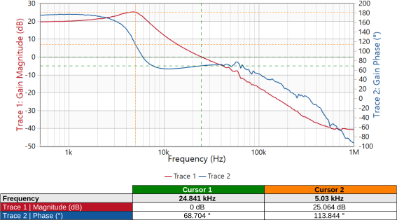
The designed ACOT control loop is validated using frequency-domain measurements, as shown in the Bode plot. The gain crosses 0 dB at approximately 24.8 kHz, which closely matches the targeted crossover frequency selected during the design process. At this point, the measured phase margin is around 68°, indicating a stable control loop with sufficient margin for robust operation.
The second zero (FZ2) is observed around 13 kHz, providing the intended phase boost prior to crossover. The gain and phase characteristics confirm that the placement of poles and zeros, along with the selected ripple injection components (CINJ = 15 nF, RINJ = 200 kΩ, CFF = 560 pF), successfully shape the loop response as predicted by the analytical design. This validates the effectiveness of the frequency-domain design approach in achieving the desired loop stability.
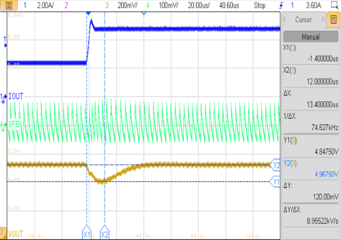
The transient performance of the converter is evaluated using a load step from 2.5 A to 5 A with a fast transition time. The measured output voltage waveform shows an undershoot of approximately 120 mV, followed by a recovery within about 13.4 µs, and a settling time of approximately 30 µs.
The ripple waveform at the feedback node remains well-defined, confirming proper ripple injection and stable comparator operation during dynamic conditions. These results demonstrate that the designed control loop not only meets stability requirements but also delivers fast transient response, highlighting the trade-off achieved between crossover frequency, phase margin, and ripple amplitude. Overall, the measured performance aligns well with the design expectations, confirming the validity of the analytical and frequency-domain design methodology.