
1.5 PMSM FOC with Single Shunt Current Reconstruction
This application implements the sensor-less field oriented control (FOC) of a permanent magnet synchronous motor (PMSM). It estimates rotor position from measured phase currents and a PLL based estimator. The feedback motor phase currents are calculated from single shunt current reconstruction methodology. This algorithm is implemented on a PIC32MK MCU.
Description
Permanent Magnet Synchronous Motor (PMSM) is controlled using Field Oriented Control (FOC). Rotor position and speed is determined using PLL based estimator. The PMSM motor current is determined by single shunt current reconstruction method. Motor start/stop operation is controlled by the switch and motor speed can be changed by the on-board potentiometer. Waveforms and variables can be monitored run time using X2CScope.
Key features enabled in this project are:
- Single shunt current measurement
- Speed control loop
MCC Project Configurations
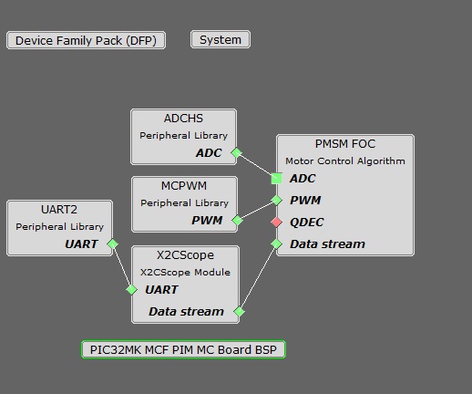
- PMSM_FOC:
This component configures FOC algorithm parameters, motor parameters and motor control board parameters. It connects to underlying peripheral libraries ADCHS and MCPWM. This components auto configures ADC channels and PWM channels as per PMSM_FOC component configurations.
- ADCHS Peripheral:
- The ADCHS is used to measure analog quantities. Three channels are used to measure the DC bus current, the DC Bus Voltage and the Potentiometer.
- ADCHS convert single ended inputs. DC bus current corresponds to time during T1 and T2 is sampled and converted by ADCHS Channel 0.
- ADCHS Channel 0 is hardware triggered by MCPWM in dual trigger mode.
- Conversion Ready interrupt is generated by ADCHS Channel 0 at time slots T1 and T2. During the ISR, the DC bus current corresponding to time slots T1 and T2 is ready, respectively.
- MCPWM Peripheral:
- Configured to generate three pairs of complimentary PWM signals at a frequency of 20 kHz in "Asymmetric Center-Aligned mode with simultaneous update".
- MCPWM Channel 2 is configured in dual trigger mode to start ADC conversion during T1 and T2 time.
- Fault functionality is also enabled to switch off the output waveforms asynchronously.
- X2Cscope:
This component adds X2C scope protocol code. This uses UART to communicate to the host PC. X2CScope allows user to monitor variables run time.
. - UART Peripheral:
The UART is used for X2CScope communication to observe graphs and variable values in run time.
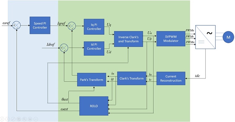
Control Algorithm
This application implements sensor-less field oriented control (FOC) of permanent magnet synchronous motor (PMSM). It estimates rotor position from measured phase currents and a PLL based estimator. The algorithm is implemented on a PIC32MK Micro-controller. The following section briefly describes the PLL based sensor-less FOC algorithm, software design and implementation.
Field Oriented Control is the technique used to achieve the decoupled control of torque and flux. This is done by transforming the stator current quantities (phase currents) from stationary reference frame to torque and flux producing current components in rotating reference frame using mathematical transformations. The Field Oriented Control is implemented as follows:
- Reconstruct the motor phase currents based on the DC bus current measurement.
- Transform the three phase currents from three phase stationary reference frame (u,v,w) into two phase stationary reference frame (alpha, beta) using the Clarke transformation.
- Estimate (sensor-less) or measure (sensored) the rotor position angle.
- Transform the stator currents from a two phase stationary reference frame (alpha, beta) into a two phase rotating reference frame (d,q) using the Park transformation. The rotating reference frame rotates synchronously with the rotor axis and therefore requires rotor angle information.
- Clarke and Park transformation allows the transformation of three phase AC stator currents into an equivalent two phase DC currents which decouples the flux (id) and torque (iq) producing components of the stator currents.
- The stator current torque (iq) and flux (id) producing components are regulated independently by two independent PI controllers. These PI controllers generate an output voltage reference in d,q reference frame which is transformed into three phase stationary frame AC voltages using the inverse park and inverse clarke transformations.
- In order to increase the DC bus utilization, the three phase sinusoidal AC output voltages are translated into space vector modulated voltages and applied across the stator windings using a Three Phase Half-Bridge Inverter.
Rotor Position and Speed Estimation:
The Back EMF with PLL is a technique where the BEMF is used to estimate speed and position. It is based on the principle that when the stator and rotor magnetic fluxes are orthogonal to each other, the BEMF across the d-axis is '0'. The PLL is used to drive d-axis BEMF to zero, thereby estimating the rotor position and speed. For more details refer Application note AN2520.
Single Shunt Current Reconstruction:


The single shunt current reconstruction requires a minimum active vector time ( T1, T2 ) for shunt current to be stabilized before it can be sampled as shown above. To avoid shunt current ripples issue to creep into the ADC measurement, the calculated SVPWM is adjusted asymmetrically . Asymmetric adjustment of SVPWM for different scenarios is described below:


The implementation details of single shunt current reconstruction can be referred from the Application note AN1299.
Software Design
The following figure shows the flow chart of the implemented algorithm:
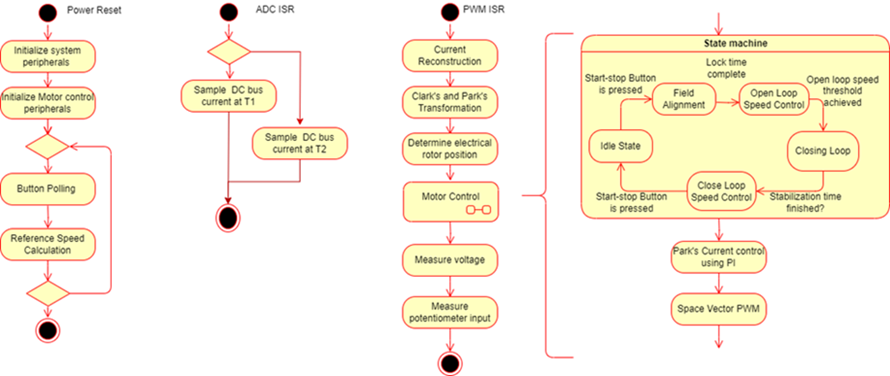
Field Alignment - ALIGN:
In this mode, a pre-defined value of the current is asserted across the Q axis of the rotor for a pre-defined length of time, in order to align the rotor to a known angle of 90 electrical degrees. The magnitude of the current and the length of the time for which it is applied depends upon the electrical and mechanical time constant of the PMSM motor drive. Electrical time constant of the motor is a function of R and L values of the motor windings, whereas the mechanical time constant of the motor drive is primarily a function of the static load on the motor shaft.
Open Loop Control - STARTING:
In this mode, the speed of the PMSM motor is gradually ramped up using an open loop control. During this mode, the rotor angle is derived from the asserted open loop speed reference. This derived rotor angle would be lagging from the actual rotor angle. The speed is ramped up linearly to a minimum value required for the PLL-based estimator to estimate the alpha and beta axis back EMF of the PMSM motor with sufficient accuracy. Rotor angle information is extracted from arctan(BEMFbeta/ BEMFalpha).
Close Loop Control - RUNNING:
In this mode, the estimated rotor angle obtained from PLL-based estimator is used to perform field oriented control of the PMSM motor.
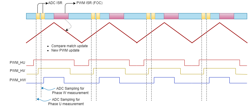
Timing Diagram:
Timing Diagram: The three critical blocks of the MCU which are involved in the motor control operations are:
- ADCHS - It measures motor phase currents at the start of the PWM cycle.
- CPU - Based on motor phase currents measurements, the CPU executes the control algorithm to calculate the PWM duty cycle needed to apply required voltage across motor windings.
- MCPWM - It generates the PWM signals needed to apply required voltage across motor windings.
The following timing diagram, shows the chronological role played by the ADC, CPU and MCPWM in the execution of FOC algorithm.
Development Kits
MCLV2 with PIC32MK Family Motor Control PIM
DOWNLOADING AND BUILDING THE APPLICATION
To clone or download this application from Github, go to the main page of this repository and then click Clone button to clone this repository or download as zip file. This content can also be downloaded using content manager by following these instructions.
Path of the application within the repository is apps/pmsm_foc_pll_1shunt_pic32_mk.
To build the application, refer to the following table and open the project using its IDE.
| Project Name | Description | Demo User Guide |
|---|---|---|
| mclv2_pic32mk_mcf_pim.X | MPLABX project for MCLV2 board with PIC32MK MCF PIM | MCLV2 with PIC32MK MCF PIM |
| mclv2_pic32mk_mcm_pim.X | MPLABX project for MCLV2 board with PIC32MK MCM PIM | MCLV2 with PIC32MK MCM PIM |
| mclv2_pic32mk_mca_pim.X | MPLABX project for MCLV2 board with PIC32MK MCA PIM | MCLV2 with PIC32MK MCA PIM |
| mclv_48v_pic32mk_mca_dim.X | MPLABX project for 48V MCLV board with PIC32MK MCA DIM | MCLV_48V_300W with PIC32MK MCA DIM |
| mclv_48v_pic32mk_mcm_dim.X | MPLABX project for 48V MCLV board with PIC32MK MCM DIM | MCLV_48V_300W with PIC32MK MCM DIM |