2 Running the Demo
(Ask a Question)Prerequisites for the procedure:
- On the host PC, download and install the Microchip Power Monitor application from Power Monitor Application.
- Ensure that the jumper settings on the board are same as listed in the following table:
Table 2-1. Jumper Settings Jumper Description J18, J19, J20, J21, and J22 Close Pins 2 and 3 for Programming PolarFire® FPGA through FTDI. J28 Close Pins 1 and 2 for programming through the on board FlashPro5. J4 Close Pins 1 and 2 for manual power switching using switch SW3. J12 Close Pins 3 and 4 for 2.5V - Connect the power supply cable to the J9 connector on the board.
- Connect the USB cable from the Host PC to the J5 (FTDI port) on the board.
- Power on the board using the SW3 slide switch.
To run the demo, perform the following steps:
- Ensure DIP-3 and DIP-4 are ON and DIP-1 and DIP-2 are OFF.Important: In Evaluation Kit, DIP switches are active-low.
- To program the design without low-power options (
PF_Demo_Normal.job) using FlashPro Express, see Appendix 1: Programming the Device Using FlashPro Express. - The LEDs {4, 5}, {6, 7}, {8, 9} and {10,11} blink at different rates. This indicates that the fabric components are in Active mode.
- On the host PC desktop, click Start and then select PowerMonitor.
- In the COMPort SetUp dialog box, select the highest COM port from the drop-down and click Connect, as shown in the following figure.
Figure 2-1. COMPort SetUp 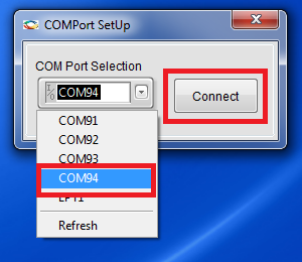
The PowerMonitor application successfully connects to the board and starts displaying the Core Fabric (VDD) power, Fabric PLL (VDD25) power, Transceiver Core (VDDA) power and Transceiver PLL (VDDA25) power.
The total power consumed by the device is displayed in the PowerMonitor GUI, as shown in the following figure.Figure 2-2. Total Power—PolarFire Normal Demo 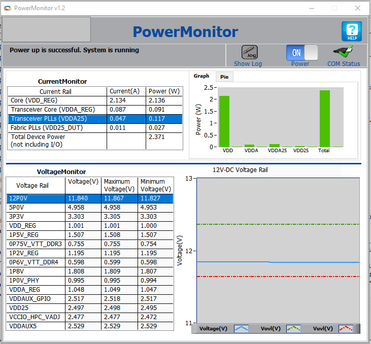
- To program the design with Low-power options (
PF_Demo_Low_power.job) using FlashPro Express, see Appendix 1: Programming the Device Using FlashPro Express section.The total power consumed by the device is displayed in the PowerMonitor GUI.
Figure 2-3. Total Power—PolarFire Low-Power Demo 
- Turn off XCVR and TX PLL by changing DIP-3 OFF and measure power.
The total power consumed by the device is displayed in the PowerMonitor GUI.
Figure 2-4. Total Power—XCVR and TX PLL 
- Turn on clock gating by changing DIP-2 ON and measure power.
- The LEDs {8, 9}, blink at different rates as the clock is available. The LEDs {4, 5}, {6, 7} and {10,11} maintain previous state as the clocks are not available.
The total power consumed by the device is displayed in the PowerMonitor GUI.
Figure 2-5. Total Power—Clock Gating 
- Make CCC in Power-Down mode by changing DIP-1 ON and measure power.
The total power consumed by the device is displayed in the PowerMonitor GUI.
Figure 2-6. Total Power—Power Down Mode 
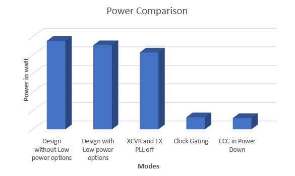
The following table lists the percentage of change after performing the preceding steps.
| Modes | Percentage of Power Saved After Each Step (Approximately) |
|---|---|
| Design without Low-power options | — |
| Design with Low-power options | 5.0 |
| XCVR and TX PLL off | 9.0 |
| Clock Gating | 84.0 |
| CCC in Power Down | 6.0 |
The following figure shows the graphical comparison of the power in various modes.