2.3 I/O Pins
These components are used to enable the I/O operations the bootloader implements during
execution.
Entry Pin: The Input pin (ENTRY pin) is generally used to control a push button or similar peripheral on the board that forces the bootloader into a boot-ready state. This functionality is often used during development, but it is usually not the best solution for the field. The system needs to be built to be able to move back and forth from the bootloader to the application without the user needing to force an entry.
Indicator Pin: The Output pin (INDICATE pin) is used to tell the bootloader user what state the bootloader is currently in. Usually an LED is connected to indicate the state of the system. The Pin Grid View tab gives a higher level of control over the configuration of the pin on the device, which means the user can activate these pins through software as well. It is always recommended to develop the application code using an indicator on the bootloader, but it is usually not necessary once in the field, unless that type of status indication is needed for the solution.
Example: There are three main steps to configuring the I/O pins for the bootloader. First, enable the Pin Indicator and Pin Entry options on the MCC UI, then use the Pin Grid View tab to select a port number on the device that the I/O pins will use. Lastly, validate the correct configuration of the chosen pin.
Configuring I/O Pins
-
Enable pins from UI.
Figure 2-5. I/O Options 
-
Select a port.
Any of the pins in the Pin Grid View tab can be chosen, as long as the pin is not responsible for other functionalities in the MCU used. Refer to the specific device data sheet for additional information about the port settings. Refer to the Use Case Example for an in-depth description of this process.
Figure 2-6. Pin Grid View 
-
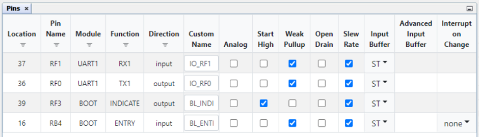
Open Pins UI.
Figure 2-7. Pins UI 
-
Check the pins.
Figure 2-8. Pins UI Window