
3.2 User Reset Generation Schemes
(Ask a Question)The User Reset Generation Schemes are as follows:
- If the design uses an external reset input, the reset input must be ignored
until the input buffer of the RESET signal is known to be operational. This is
applicable for the following conditions:
- FABRIC_POR_N negates
- BANK_x_VDDI_STATUS asserts (where x is the number of the I/O bank containing the input buffer)
- If the design uses a PLL with an external reference clock input, the PLL must
be held in power-down state from the FPGA fabric until the external reference clock
is stable and the input buffer of the external reference clock is known to be
operational. The input buffer is operational when the latter of the following two
conditions occur:
- FABRIC_POR_N negates
- BANK_y_VDDI_STATUS asserts (where y is the number of the I/O bank containing the input buffer)
- If the DRI_CLK is generated by a flip-flop in the FPGA fabric (for example, a clock divider), this flip-flop must be asynchronously reset (for example, with FABRIC_POR_N).
- The flip-flop in the FPGA fabric that drives DRI_PSEL must be asynchronously reset (for example, with FABRIC_POR_N).
- A PLL lock signal must not be used directly as a reset signal if the PLL is configured not to emit clock pulses until after lock assertion because no clock edges occur during reset and any synchronous reset logic in the FPGA fabric is not correctly reset.
It is recommended to use CORERESET_PF to incorporate these requirements as shown in Figure 2.
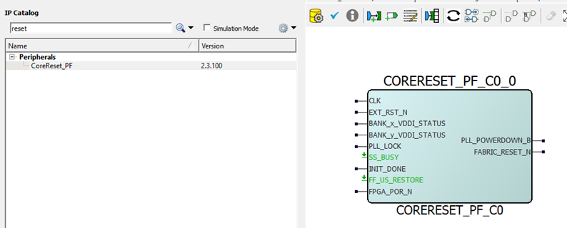
The CORERESET_PF IP core is included in the Libero IP catalog as shown in Figure 1. This IP core synchronously de-asserts the reset to the downstream logic in the user-specified clock domain. As a result, the reset assertion is asynchronous but the negation is synchronous to the clock. This IP core ensures that the recovery time is met and that all of the flip-flops come out of reset in the same clock pulse.
The CORERESET_PF IP combines the resets from multiple sources like external GPIO, PLL lock, and PF_INIT_MONITOR blocks. The CORERESET_PF IP generates system-level synchronous reset (FABRIC_RESET_N) for the fabric logic. The fabric flip-flops power-up in an indeterminate state. A reset pulse is required to force the initial state of flip-flops to a known value. The use of FABRIC_RESET_N for this reset is recommended.
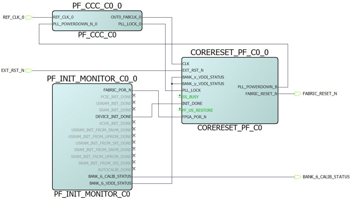
PolarFire Initialization Monitor (PF_INIT_MONITOR component) must be instantiated in all designs and can be used to reset the user logic. The following figure shows an example use case of PF_INIT_MONITOR. In this example, the DEVICE_INIT_DONE signal is connected to the INIT_DONE signal of the RESET_GEN_0 block (CORERESET_PF IP) to give a synchronous reset signal to the user logic. The DEVICE_INIT_DONE signal gets asserted after the completion of device initialization.
In this example, EXT_RST_N and REF_CLK are connected to Bank 6. BANK_x_VDDI_STATUS and BANK_y_VDDI_STATUS are connected to Bank_6_VDDI_STATUS by enabling the Bank_6_VDDI_STATUS in PF_INIT MONITOR IP. Bank6_CALIB_STATUS can be used for monitoring the GPIO calibration status, if any of the GPIO is connected to Bank6.
When using the PF_CCC internal post-divider or the external feedback mode, the PLL_POWERDOWN_N input must be controlled and de-asserted synchronously. The following modification is recommended:
- Gate the PLL_POWERDOWN_B signal of the CORERESET_PF IP core by the DEVICE_INIT_DONE signal of the PF_INIT_MONITOR IP core
- Synchronize using two flip-flops to the clock (REF_CLK_0) before connecting to the PLL_POWERDOWN_N_0 signal
The following figure shows a sample use case of PF_INIT_MONITOR and CORERESET_PF connected to PF_CCC configured in the internal post-divider or the external feedback mode.
