
1.4.1.6 CAN Bootloader Protocol
Request Packet
The can bootloader protocol as shown in below figure is common for all the supported commands.

Command
-
Indicates the command to be processed. Each command is of 1 Byte width.
-
Below are the supported commands
Command Type Command Code Description Unlock 0xA0 Used to calculate application start address and end address Data 0xA1 Used to send the image data Verify 0xA2 Used to verify the image data sent and programmed Reset 0xA3 Used to trigger a reset to run the application Bank Swap and reset 0xA4 Used to Swap the bank and trigger a reset to run the application Device Configuration 0xA5 Used to send the device configuration bits (Fuse Settings) Read Version 0xA6 Used to read the bootloader version running
Sequence Number
-
Indicates the packet sequence number
-
For data command the sequence number has to be incremented by 1 for every data packet. Bootloader checks the sequence number once data packet is recieved. If there is a mismatch it sends a sequence error response.
-
As the sequence number is of 1 Byte width, once it reaches to a value of 255 it restarts from zero
GUARD
-
The Guard value must be a constant value of 0xE2
-
This value provides protection against spurious commands
-
Bootloader always checks for the Guard value on packet reception and proceeds further accordingly
Data Size
-
This field indicates the number of data bytes to be received
-
This value varies for different commands
Data
-
Contains the actual Data to be processed based on the command
-
Length of the data to be received is indicated by Data Size field
-
All data words must be sent in a little-endian (LSB first) format
Response Codes
Bootloader will send a single character response code in response to each command. Sequential commands can only be sent after the response code is received for a previous command, or after 100 ms timeout without a response.
| Response Type | Response Code | Description |
|---|---|---|
| OK | 0x50 | Command was received and processed successfully |
| Error | 0x51 | There were errors during the processing of the command |
| Invalid | 0x52 | Invalid command is received |
| CRC OK | 0x53 | CRC verification was successful |
| CRC Fail | 0x54 | CRC verification failed |
| SEQ ERROR | 0x55 | Sequence number mismatch for Data command |
Unlock Command
The Unlock command sequence is as shown in below figure with corresponding responses.
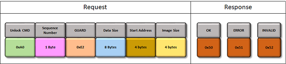
-
Unlock command must be issued before the first Data command
-
It is used to calculate application start address and end address
-
This information will be used to validate if the addresses sent are within the range of Flash memory
-
-
Number of bytes of data to be received is 8 Bytes (Start Address + Image Size)
-
Start Address
- It is the application Start Address of the Flash memory
- It is device dependent and should be always greater than or equal to the bootloader end address
- It must be aligned at an Erase Unit Size boundary, which is also device dependent
- To upgrade the bootloader itself this value must be set to 0 (For Cortex-M based MCUs)
-
Image size must be in increments of Erase Unit bytes which is also device dependent
Data Command
The Data command sequence is as shown in below figure with corresponding responses.
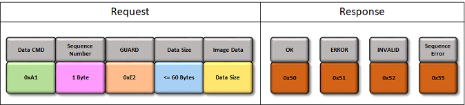
-
Data command is used to send the image data
-
The maximum packet length received by CAN bootloader is 64Bytes. The Data size <= 60Bytes as it has 4 bytes reserved for packet header.
Verify Command
The Verify command sequence is as shown in below figure with corresponding responses.
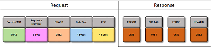
-
Verify command is used to verify the image data sent and programmed
-
Image CRC is a standard IEEE CRC32 with a polynomial of 0xEDB88320
-
Internal CRC is calculated based on the values actually read from the Flash memory after programming, so it verifies the whole chain
-
Image CRC is calculated over the previously unlocked region
Reset Command
The Reset command sequence is as shown in below figure with corresponding responses.
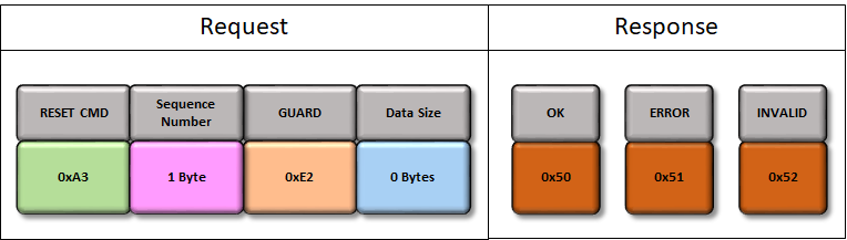
-
Reset command is used to exit the bootloader and run the application
-
It is necessary if the host has no control over the reset pin. It can also be useful even if host has control over the Reset
Bank Swap and Reset Command
The Bank Swap and Reset command sequence is as shown in below figure with corresponding responses.
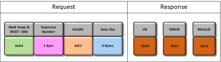
-
This command is enabled only when Fail safe update feature is selected for bootloader and the device has support for Dual Bank update
-
Bank Swap and Reset command is used to Swap the inactive bank to active bank and trigger a reset to exit the bootloader and run the new application programmed in the inactive bank
Device Configuration Command (For Cortex-M based MCU's)
The Device Configuration command sequence is as shown in below figure with corresponding responses.
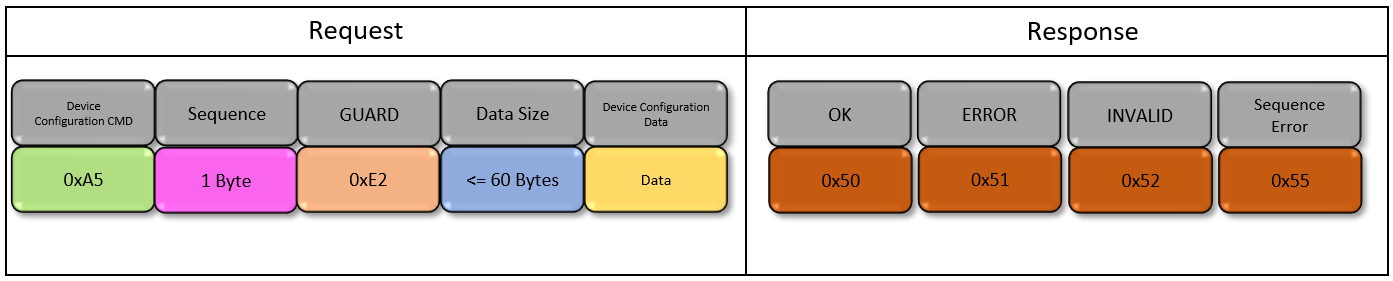
-
This command is enabled only when Enable Fuse Programming feature is selected for bootloader
-
Device Configuration command is used to send the device configuration bits (Fuse Settings)
-
Data size is equal to sum of device config area start address (4 Bytes) and Erase Unit Size which is device dependent. The maximum packet length received by CAN bootloader is 64Bytes. The Data size <= 60Bytes as it has 4 bytes reserved for packet header.
-
Device configuration data should contain all the fuse settings applicable for the device. Partial Fuse bit programming is not supported.
-
Attempts to request the write outside of the device configuration area will result in error and supplied data will be discarded
-
Refer to the Bootloader Device Configuration Input section for details on creating the Device Configuration Input text file
Read Version Command
The Read Version command sequence is as shown in below figure with corresponding responses.
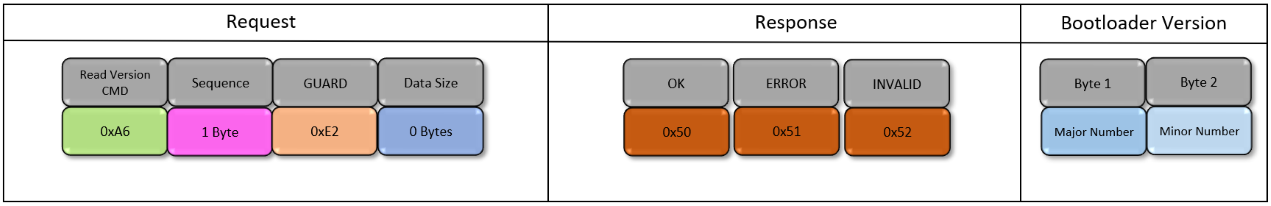
-
Read version command is used to read the current version of bootloader running on the device
-
There is not data to be sent to the device, so size is 0 bytes
-
On receiving this command
-
Bootloader will first send one of the responses mentioned above for the command
-
Once the OK response is received, Host needs to read 2 bytes for getting the bootloader version
- Byte 1 is the Major number
- Byte 2 is the Minor number
-