
1.4.4.3 Application Linker Configurations for MIPS Based MCUs
Bootloader placement for various PIC32M product families
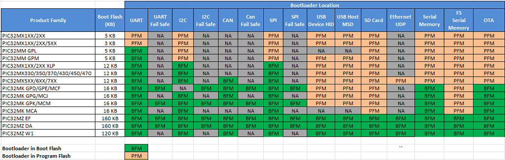
The bootloader is placed in Boot Flash Memory (BFM) or Program Flash Memory (PFM) based on the size of the bootloader and available BFM on the device.
-
If the bootloader fits into the available BFM, it is placed in BFM. The user application can use the complete area of the PFM.
-
If the bootloader does not fit into the available BFM, it is placed in PFM. The user application can use the remaining area of the PFM.
-
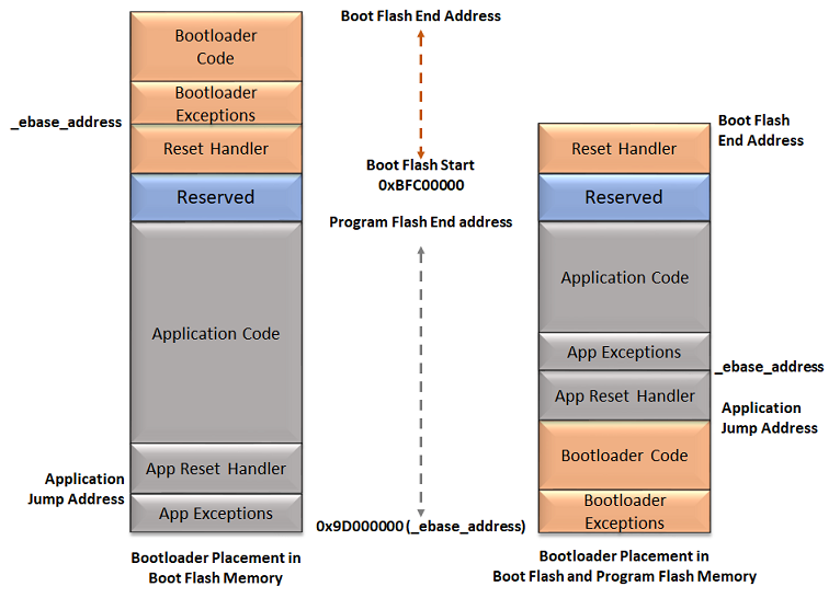
The bootloader exceptions have to be placed at the _ebase_address of bootloader memory region
-
The application exceptions have to be placed at the _ebase_address of application memory region
-
-
The following table shows the available BFM and the placement of different bootloaders by product family
Basic Memory layout
Setting up the Application linker script
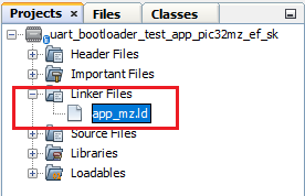
The linker script file of the application project has to be modified to place the exceptions, vector table and reset handlers in PFM.
- For quick start, refer to the pre
developed application linker scripts app_XX.ld placed in projects device
specific configuration folder of bootloader_apps_xxx/ repository. For
example:
-
Reset handler address for the application to be loaded through bootloader should match the Application Jump address mentioned in bootloader project
-
The vector address of a given interrupt is calculated using Exception Base (EBASE) CPU register and the _ebase_address should be aligned to 4 KB boundary
For Bootloaders placed in Boot Flash Memory (PIC32MZ and PIC32MK Devices)
-
The application start address and _ebase_address by default will be start of PFM. The application exceptions are stored here aligning to offsets from _ebase_address as per device architecture.
- Refer to the specific device Data Sheet for PFM start address and length
-
The application reset handler will be stored at application jump address after the exceptions at offset 0x200. The bootloader will always jump to application jump address to run the application.
-
4 KB of memory is reserved from Application jump address for Reset Handler and cache_init section
-
XC32 Compiler calculates offset from the EBASE address and initializes the value of interrupt vector offset (OFFx) register. The offset register is combined with EBASE register using a bitwise OR operator to obtain the interrupt vector address that the CPU will jump to when the corresponding interrupt occurs.
-
If the EBASE address is aligned to 4 KB, then all the interrupt vectors must be located within the 4 KB from base address
- For example, when _ebase_address is set to 0x9D001000 and interrupts vectors are not located withing the 4 KB boundary from the ebase address (OFFx > 0x1000), then the bitwise OR operator may not provide correct interrupt vector address.
-
To provide maximum flexibility in placement of interrupt vectors:
-
Always place the _ebase_address at start of PFM (e.g., 0x9D000000) as the default linker script
-
Exceptions have to be stored satrting from _ebase_address
-
Change the offsets of vector section to place them after the reset handler. With this the interrupt handlers can be located anywhere in the PFM.
-
-
Updated linker scripts as explained above is shown here as an exampleNote: Cache related sections are not applicable for PIC32MK devices
PROVIDE(_vector_spacing = 0x0001);
PROVIDE(_ebase_address = 0x9D000000);

/* Place the vector table and other exceptions after the device reset and
 * cache init code.
 */
PROVIDE(_ebase_vector_offsets = 0x1200);

_RESET_ADDR                    = 0xBD000200;
_SIMPLE_TLB_REFILL_EXCPT_ADDR  = _ebase_address + 0;
_CACHE_ERR_EXCPT_ADDR          = _ebase_address + 0x100;
_GEN_EXCPT_ADDR                = _ebase_address + 0x180;

/* Place the exceptions starting from _ebase_address as required by device specification */
kseg0_exception_mem (rx) : ORIGIN = 0x9D000000, LENGTH = 0x200

kseg1_boot_mem           : ORIGIN = 0xBD000200, LENGTH = 0x480
kseg1_boot_mem_4B0       : ORIGIN = 0xBD000680, LENGTH = 0x1000 - 0x4B0

kseg0_program_mem  (rx)  : ORIGIN = 0x9D001200, LENGTH = 0x200000 - 0x1200

/* Boot Sections */
.reset _RESET_ADDR :
{
  KEEP(*(.reset))
  KEEP(*(.reset.startup))
} > kseg1_boot_mem

.cache_init :
{
  *(.cache_init)
  *(.cache_init.*)
} > kseg1_boot_mem_4B0

.simple_tlb_refill_excpt _SIMPLE_TLB_REFILL_EXCPT_ADDR :
{
  KEEP(*(.simple_tlb_refill_vector))
} > kseg0_exception_mem

.cache_err_excpt _CACHE_ERR_EXCPT_ADDR :
{
  KEEP(*(.cache_err_vector))
} > kseg0_exception_mem

.app_excpt _GEN_EXCPT_ADDR :
{
  KEEP(*(.gen_handler))
} > kseg0_exception_mem

/* Interrupt vector table with vector offsets */
.vectors _ebase_address + _ebase_vector_offsets + 0x200 :
{
  /*  Symbol __vector_offset_n points to .vector_n if it exists,
   *  otherwise points to the default handler. The
   *  vector_offset_init.o module then provides a .data section
   *  containing values used to initialize the vector-offset SFRs
   *  in the crt0 startup code.
   */
  . = ALIGN(4) ;
  __vector_offset_0 = (DEFINED(__vector_dispatch_0) ? (. - _ebase_address) : __vector_offset_default);
  KEEP(*(.vector_0))
  ...
  ...
  /* Default interrupt handler */
  . = ALIGN(4) ;
  __vector_offset_default = . - _ebase_address;
  KEEP(*(.vector_default))
} > kseg0_program_mem
For Bootloaders placed in Program Flash Memory (PIC32MK Devices)
-
The bootloader code resides from start of PFM. Therefore, the application start address has to be after the end of bootloader.
- Refer to the specific device Data Sheet for PFM start address and length
-
The Initial 4 KB from Application start/jump address are used by Reset Handler section. The application start address and application jump address are same in this case as the _ebase_address should be moved after the application reset handler.
-
XC32 Compiler calculates offset from the EBASE address and initializes the value of interrupt vector offset (OFFx) register. The offset register is combined with EBASE register using a bitwise OR operator to obtain the interrupt vector address that the CPU will jump to when the corresponding interrupt occurs.
-
As the bootloader is residing from start of PFM, the applications EBASE address should be moved to some 4 KB aligned offset after application reset handler. All the interrupt vectors must be located within the offset range specified from base address.
- For example, when _ebase_address is set to 0x9D002000 the interrupts vectors should be located withing the 8 KB boundary from the ebase address (OFFx > 0x2000), or else the bitwise OR operation may not provide correct interrupt vector address
-
Updated linked scripts as explained above is shown here as an example:
- Bootloader length <bootloader_length> in the below snippet needs
to be replaced with size of the respective
bootloader
PROVIDE(_vector_spacing = 0x0001);
PROVIDE(_ebase_address = 0x9D000000 + <bootloader_length> + 0x1000);

_RESET_ADDR                    = 0xBD000000 + <bootloader_length>;
_SIMPLE_TLB_REFILL_EXCPT_ADDR  = _ebase_address + 0;
_GEN_EXCPT_ADDR                = _ebase_address + 0x180;

kseg0_program_mem  (rx) : ORIGIN = 0x9D000000 + <bootloader_length> + 0x1000, LENGTH = 0x200000 - <bootloader_length> - 0x1000

kseg1_boot_mem          : ORIGIN = 0xBD000000 + <bootloader_length>, LENGTH = 0x1000

/* Boot Sections */
.reset _RESET_ADDR :
{
  KEEP(*(.reset))
  KEEP(*(.reset.startup))
} > kseg1_boot_mem

.app_excpt _GEN_EXCPT_ADDR :
{
  KEEP(*(.gen_handler))
} > kseg0_program_mem

/* Interrupt vector table with vector offsets */
.vectors _ebase_address + 0x200 :
{
  /*  Symbol __vector_offset_n points to .vector_n if it exists,
   *  otherwise points to the default handler. The
   *  vector_offset_init.o module then provides a .data section
   *  containing values used to initialize the vector-offset SFRs
   *  in the crt0 startup code.
   */
  . = ALIGN(4) ;
  __vector_offset_0 = (DEFINED(__vector_dispatch_0) ? (. - _ebase_address) : __vector_offset_default);
  KEEP(*(.vector_0))
  ...
  ...
  /* Default interrupt handler */
  . = ALIGN(4) ;
  __vector_offset_default = . - _ebase_address;
  KEEP(*(.vector_default))
} > kseg0_program_mem
- Bootloader length <bootloader_length> in the below snippet needs
to be replaced with size of the respective
bootloader
For Bootloaders placed in Boot Flash Memory (PIC32MX and PIC32MM Devices)
-
The application start address by default will be start of PFM
- Refer to the specific device Data Sheet for PFM start address and length
-
The Initial 4 KB are used by Reset Handler section
-
In PIC32MX devices the _ebase_address holds the start address of vector table and it must be placed at 4 KB boundary after the Reset Handler section
-
Updated linked scripts as explained above is shown here as an example:
PROVIDE(_vector_spacing = 0x0001);
PROVIDE(_ebase_address = 0x9D001000);

_RESET_ADDR                 = 0xBD000000

kseg0_program_mem     (rx)  : ORIGIN = 0x9D001000, LENGTH = 0x80000 - 0x1000
kseg1_boot_mem              : ORIGIN = 0xBD000000, LENGTH = 0x1000

/* Boot Sections */
.reset _RESET_ADDR :
{
  KEEP(*(.reset))
  KEEP(*(.reset.startup))
} > kseg1_boot_mem
...

.vector_0 _ebase_address + 0x200 + ((_vector_spacing << 5) * 0) :
{
   KEEP(*(.vector_0))
} > kseg0_program_mem
ASSERT (_vector_spacing == 0 || SIZEOF(.vector_0) <= (_vector_spacing << 5), "function at exception vector 0 too large")

.vector_1 _ebase_address + 0x200 + ((_vector_spacing << 5) * 1) :
{
   KEEP(*(.vector_1))
} > kseg0_program_mem
ASSERT (_vector_spacing == 0 || SIZEOF(.vector_1) <= (_vector_spacing << 5), "function at exception vector 1 too large")
...
...
For Bootloaders placed in Program Flash Memory (PIC32MX and PIC32MM Devices)
-
The bootloader code resides from start of PFM. Therefore, the application start address has to be after the end of bootloader
-
The Initial 4 KB from Application start address are used by Reset Handler section
-
Place the _ebase_address after the device startup code of application
-
Updated linked scripts as explained above is shown here as an example:
- Bootloader length <bootloader_length> in the below snippet needs to be replaced with size of the respective bootloader
PROVIDE(_vector_spacing = 0x0001);
PROVIDE(_ebase_address = 0x9D000000 + <bootloader_length> + 0x1000);

_RESET_ADDR                 = 0xBD000000 + <bootloader_length>;

kseg0_program_mem     (rx)  : ORIGIN = 0x9D000000 + <bootloader_length> + 0x1000, LENGTH = 0x80000 - <bootloader_length> - 0x1000
kseg1_boot_mem              : ORIGIN = 0xBD000000 + <bootloader_length>, LENGTH = 0x1000

/* Boot Sections */
.reset _RESET_ADDR :
{
  KEEP(*(.reset))
  KEEP(*(.reset.startup))
} > kseg1_boot_mem
...

.vector_0 _ebase_address + 0x200 + ((_vector_spacing << 5) * 0) :
{
   KEEP(*(.vector_0))
} > kseg0_program_mem
ASSERT (_vector_spacing == 0 || SIZEOF(.vector_0) <= (_vector_spacing << 5), "function at exception vector 0 too large")

.vector_1 _ebase_address + 0x200 + ((_vector_spacing << 5) * 1) :
{
   KEEP(*(.vector_1))
} > kseg0_program_mem
ASSERT (_vector_spacing == 0 || SIZEOF(.vector_1) <= (_vector_spacing << 5), "function at exception vector 1 too large")
...
...
-
The bootloader and the application must have the same device configuration bit settings. The Device configuration bit settings from the bootloader project will be updated by the programmer/debugger. Therefore, the application linker script should not have any device configuration bit settings. The application project will use the device configuration bit settings done by bootloader.
-
Device configurations and debug exception need to discarded from final hex file for the application project
/DISCARD/ : { *(._debug_exception) }
/DISCARD/ : { *(.config_*) }
Additional settings (Optional)
- Data Memory Origin and Data Memory Length values should be updated in linkerscript
for reserving configured bytes from start of RAM to trigger bootloader from
firmware
/* Reserve <trigger_len> Bytes to Store Bootloader Trigger Pattern */
kseg0_data_mem       (w!x)  : ORIGIN = <ram_start> + <trigger_len>, LENGTH = <ram_length> - <trigger_len>