
1.7.3.1 Bootloader Linker Configurations for MIPS Based MCUs
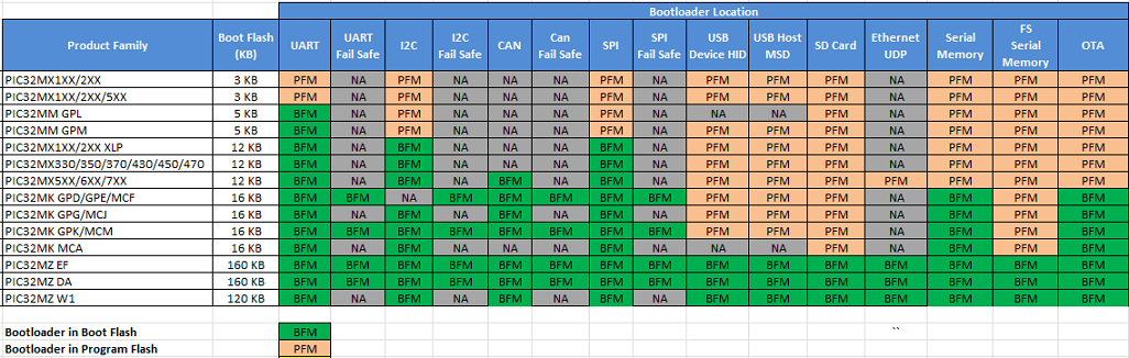
Bootloader placement for various PIC32M product families
The bootloader is placed in BFM or PFM based on the size of the bootloader and available BFM on the device.
-
If the bootloader fits into the available BFM, it is placed in BFM. The user application can use the complete area of the PFM.
-
If the bootloader does not fit into the available BFM, it is placed in PFM. The user application can use the remaining area of the PFM.
The following table shows the available BFM and the placement of different bootloaders by product family.
Bootloader linker script settings
-
Bootloader library uses a custom linker script which is generated through MCC
-
The values populated in the linker script are based on the Bootloader component MCC configurations
-
The vector address of a given interrupt is calculated using Exception Base (EBASE) CPU register and the _ebase_address should be aligned to 4 KB boundary
Note: The below sections provides overview of changes done to bootloader linker scripts when compared to default linker script. The address location and size may vary based on the specific device used.
For Bootloaders placed in Boot Flash Memory (PIC32MZ and PIC32MK Devices)
-
The bootloader start address by default will be start of BFM (0xBFC00000). This is the default startup location for all PIC32M devices.
-
The Initial 4 KB from Bootloader start address are used by Reset Handler and cache_init section followed by rest of bootloader code
-
Length of the bootloader is calculated based on the bootloader being added to MCC
-
XC32 Compiler calculates offset from the EBASE address and initializes the value of interrupt vector offset (OFFx) register. The offset register is combined with EBASE register using a bitwise OR operator to obtain the interrupt vector address that the CPU will jump to when the corresponding interrupt occurs.
-
Generated linker scripts as explained above is shown here as an example
-
Bootloader length <bootloader_length> in the below snippet is auto generated based on the bootloader component added in MCC
Note: Cache related sections are not applicable for PIC32MK Devices.
PROVIDE(_vector_spacing = 0x0001);
PROVIDE(_ebase_address = 0x9FC01000);

_RESET_ADDR                    = 0xBFC00000;
_BEV_EXCPT_ADDR                = 0xBFC00380;
_DBG_EXCPT_ADDR                = 0xBFC00480;
_SIMPLE_TLB_REFILL_EXCPT_ADDR  = _ebase_address + 0;
_CACHE_ERR_EXCPT_ADDR          = _ebase_address + 0x100;
_GEN_EXCPT_ADDR                = _ebase_address + 0x180;

kseg0_program_mem  (rx) : ORIGIN = 0x9FC01000, LENGTH = <bootloader_length>

kseg1_boot_mem          : ORIGIN = 0xBFC00000, LENGTH = 0x480

kseg1_boot_mem_4B0      : ORIGIN = 0xBFC004B0, LENGTH = 0x1000 - 0x4B0
...
config_BFC0FF40             : ORIGIN = 0xBFC0FF40, LENGTH = 0x4
config_BFC0FF44             : ORIGIN = 0xBFC0FF44, LENGTH = 0x4
config_BFC0FF48             : ORIGIN = 0xBFC0FF48, LENGTH = 0x4
...
...

SECTIONS
{
  .config_BFC0FF40 : {
    KEEP(*(.config_BFC0FF40))
  } > config_BFC0FF40
  .config_BFC0FF44 : {
    KEEP(*(.config_BFC0FF44))
  } > config_BFC0FF44
...
...
}

/* Boot Sections */
.reset _RESET_ADDR :
{
  KEEP(*(.reset))
  KEEP(*(.reset.startup))
} > kseg1_boot_mem

.cache_init :
{
  *(.cache_init)
  *(.cache_init.*)
} > kseg1_boot_mem_4B0
...

/* Interrupt vector table with vector offsets */
.vectors _ebase_address + 0x200 :
{
  /*  Symbol __vector_offset_n points to .vector_n if it exists,
   *  otherwise points to the default handler. The
   *  vector_offset_init.o module then provides a .data section
   *  containing values used to initialize the vector-offset SFRs
   *  in the crt0 startup code.
   */
  . = ALIGN(4) ;
  __vector_offset_0 = (DEFINED(__vector_dispatch_0) ? (. - _ebase_address) : __vector_offset_default);
  KEEP(*(.vector_0))
  ...
  ...
  /* Default interrupt handler */
  . = ALIGN(4) ;
  __vector_offset_default = . - _ebase_address;
  KEEP(*(.vector_default))
} > kseg0_program_mem
-
For Bootloaders placed in Program Flash Memory (PIC32MK Devices)
-
The bootloader start address by default will be start of BFM (0xBFC00000). This is the default startup location for all PIC32M devices.
-
As the entire bootloader cannot be placed in BFM. Only the bootloader Reset Handler is placed in BFM. Rest of the bootloader code along with exceptions and vector table will be placed from start of PFM.
-
XC32 Compiler calculates offset from the EBASE address and initializes the value of interrupt vector offset (OFFx) register. The offset register is combined with EBASE register using a bitwise OR operator to obtain the interrupt vector address that the CPU will jump to when the corresponding interrupt occurs.
-
To provide maximum flexibility in placement of interrupt vectors:
- The _ebase_address is placed at start of PFM (e.g., 0x9D000000), such as the default linker script
-
Generated linker scripts as explained above is shown here as an example
- Bootloader length <bootloader_length> in the below snippet is auto generated based on the bootloader component added in MCC
PROVIDE(_vector_spacing = 0x0001);
PROVIDE(_ebase_address = 0x9D000000);

_RESET_ADDR                    = 0xBFC00000;
_BEV_EXCPT_ADDR                = 0xBFC00380;
_DBG_EXCPT_ADDR                = 0xBFC00480;
_SIMPLE_TLB_REFILL_EXCPT_ADDR  = _ebase_address + 0;
_GEN_EXCPT_ADDR                = _ebase_address + 0x180;

kseg0_program_mem  (rx) : ORIGIN = 0x9D000000, LENGTH = <bootloader_length>

kseg1_boot_mem              : ORIGIN = 0xBFC00000, LENGTH = 0x480
kseg1_boot_mem_4B0          : ORIGIN = 0xBFC004B0, LENGTH = 0x1000 - 0x4B0
...
config_BFC03F40             : ORIGIN = 0xBFC03F40, LENGTH = 0x4
config_BFC03F44             : ORIGIN = 0xBFC03F44, LENGTH = 0x4
config_BFC03F48             : ORIGIN = 0xBFC03F48, LENGTH = 0

SECTIONS
{
  .config_BFC03F40 : {
    KEEP(*(.config_BFC03F40))
  } > config_BFC03F40
  .config_BFC03F44 : {
    KEEP(*(.config_BFC03F44))
  } > config_BFC03F44
...
...
}

/* Boot Sections */
.reset _RESET_ADDR :
{
  KEEP(*(.reset))
  KEEP(*(.reset.startup))
} > kseg1_boot_mem

...

/* Interrupt vector table with vector offsets */
.vectors _ebase_address + 0x200 :
{
  /*  Symbol __vector_offset_n points to .vector_n if it exists,
   *  otherwise points to the default handler. The
   *  vector_offset_init.o module then provides a .data section
   *  containing values used to initialize the vector-offset SFRs
   *  in the crt0 startup code.
   */
  . = ALIGN(4) ;
  __vector_offset_0 = (DEFINED(__vector_dispatch_0) ? (. - _ebase_address) : __vector_offset_default);
  KEEP(*(.vector_0))
  ...
  ...
  /* Default interrupt handler */
  . = ALIGN(4) ;
  __vector_offset_default = . - _ebase_address;
  KEEP(*(.vector_default))
} > kseg0_program_mem
For Bootloaders placed in Boot Flash Memory (PIC32MX and PIC32MM Devices)
-
The bootloader start address by default will be start of BFM (0xBFC00000). This is the default startup location for all PIC32M devices.
-
The Initial memory from Bootloader start address are used by Reset Handler and then followed by rest of bootloader code
-
Length of the bootloader is calculated based on the bootloader being added to MCC
-
The _ebase_address holds the start address of vector table and it must be placed at 4 KB boundary after the Reset Handler section
-
Generated linker scripts as explained above is shown here as an example
- Bootloader length <bootloader_length> in the below snippet is auto generated based on the bootloader component added in MCC
PROVIDE(_vector_spacing = 0x0001);
PROVIDE(_ebase_address = 0x9FC01000);

_RESET_ADDR                    = 0xBFC00000;
_BEV_EXCPT_ADDR                = 0xBFC00380;
_DBG_EXCPT_ADDR                = 0xBFC00480;
_DBG_CODE_ADDR                 = 0xBFC02000;
_DBG_CODE_SIZE                 = 0xFF0;
_GEN_EXCPT_ADDR                = _ebase_address + 0x180;

kseg0_program_mem     (rx)  : ORIGIN = 0x9FC00500, LENGTH = <bootloader_length>
kseg1_boot_mem              : ORIGIN = 0xBFC00000, LENGTH = 0x490
...
config3                     : ORIGIN = 0xBFC02FF0, LENGTH = 0x4
config2                     : ORIGIN = 0xBFC02FF4, LENGTH = 0x4

SECTIONS
{
  .config_BFC02FF0 : {
    KEEP(*(.config_BFC02FF0))
  } > config3
  .config_BFC02FF4 : {
    KEEP(*(.config_BFC02FF4))
  } > config2
}

/* Boot Sections */
.reset _RESET_ADDR :
{
  KEEP(*(.reset))
  KEEP(*(.reset.startup))
} > kseg1_boot_mem
...

.vector_0 _ebase_address + 0x200 + ((_vector_spacing << 5) * 0) :
{
   KEEP(*(.vector_0))
} > kseg0_program_mem
ASSERT (_vector_spacing == 0 || SIZEOF(.vector_0) <= (_vector_spacing << 5), "function at exception vector 0 too large")

.vector_1 _ebase_address + 0x200 + ((_vector_spacing << 5) * 1) :
{
   KEEP(*(.vector_1))
} > kseg0_program_mem
ASSERT (_vector_spacing == 0 || SIZEOF(.vector_1) <= (_vector_spacing << 5), "function at exception vector 1 too large")
...
...
For Bootloaders placed in Program Flash Memory (PIC32MX and PIC32MM Devices)
-
The bootloader start address by default will be start of BFM (0xBFC00000). This is the default startup location for all PIC32M devices.
-
As the entire bootloader cannot be placed in BFM. Only the bootloader Reset Handler is placed in BFM. Rest of the bootloader code will be placed from start of PFM.
-
The _ebase_address is placed at start of PFM (e.g., 0x9D000000)
-
Generated linker scripts as explained above is shown here as an example
- Bootloader length <bootloader_length> in the below snippet is auto generated based on the bootloader component added in MCC
PROVIDE(_vector_spacing = 0x0001);
PROVIDE(_ebase_address = 0x9D000000);

_RESET_ADDR                    = 0xBFC00000;
_BEV_EXCPT_ADDR                = 0xBFC00380;
_DBG_EXCPT_ADDR                = 0xBFC00480;
_DBG_CODE_ADDR                 = 0x9FC00490;
_DBG_CODE_SIZE                 = 0x760;
_GEN_EXCPT_ADDR                = _ebase_address + 0x180;

kseg0_program_mem     (rx)  : ORIGIN = 0x9D000000, LENGTH = <bootloader_length>
kseg1_boot_mem              : ORIGIN = 0xBFC00000, LENGTH = 0x490
...
config3                     : ORIGIN = 0xBFC00BF0, LENGTH = 0x4
config2                     : ORIGIN = 0xBFC00BF4, LENGTH = 0x4

SECTIONS
{
  .config_BFC00BF0 : {
    KEEP(*(.config_BFC00BF0))
  } > config3
  .config_BFC00BF4 : {
    KEEP(*(.config_BFC00BF4))
  } > config2
}

/* Boot Sections */
.reset _RESET_ADDR :
{
  KEEP(*(.reset))
  KEEP(*(.reset.startup))
} > kseg1_boot_mem
...

.vector_0 _ebase_address + 0x200 + ((_vector_spacing << 5) * 0) :
{
   KEEP(*(.vector_0))
} > kseg0_program_mem
ASSERT (_vector_spacing == 0 || SIZEOF(.vector_0) <= (_vector_spacing << 5), "function at exception vector 0 too large")

.vector_1 _ebase_address + 0x200 + ((_vector_spacing << 5) * 1) :
{
   KEEP(*(.vector_1))
} > kseg0_program_mem
ASSERT (_vector_spacing == 0 || SIZEOF(.vector_1) <= (_vector_spacing << 5), "function at exception vector 1 too large")
...
...
Using Both Boot Flash Panels on PIC32MZ device
-
For PIC32MZ devices, with two 80 KB Boot Flash panels, bootloader may or may not fit entirely in one Boot Flash panel
-
In order to fit some of the Bootloaders, the linker script makes the two Boot Flash panels look as one contiguous BFM. Unimplemented areas are blocked using a fill command to the linker.
kseg0_program_mem     (rx)  : ORIGIN = 0x9FC01000, LENGTH = 0x2FF00 - 0x1000

/* Bootloader needs to be placed in both the Boot Flash Panels (lower and upper boot alias).
   Below region is used to fill 0xFF in reserved space between these two panles.
*/
protected_reg               : ORIGIN = 0x9FC14000, LENGTH = 0x20000-0x14000

...
...

SECTIONS
{
  .fill1 :
  {
    FILL(0xFF);
    . = ORIGIN(protected_reg) + LENGTH(protected_reg) - 1;
    BYTE(0xFF)
  } > protected_reg
}
-
Device configuration bits should be updated by bootloader only
-
The bootloader linker script is generated using generic templates for the device family. Generated linker script should be modified if there any changes or modifications to the specific device being used.