
4 Appendix 3: Place and Route
(Ask a Question)The place and route process requires the following steps to be completed:
- Selecting the already imported
io_constraints_FHB_DIS.pdc or
                    io_constraints_FHB_EN.pdc
file. - Placing the XCVR_Debug_0 block using the I/O Editor.
- Ensuring all the I/Os are locked.
To complete the place and route process, follow these steps:
- On the I/O Attributes tab, select the check box next to the
io_constraints_FHB_DIS.pdc or io_constraints_FHB_EN.pdcfile, as shown in the following figure. Theio_constraints_FHB_DIS.pdc or io_constraints_FHB_EN.pdcfile contains the I/O assignment for reference clock, switches and XCVR Lanes.Figure 4-1. I/O Attributes Tab 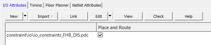
- From the Edit drop-down list, select Edit with I/O Editor, as shown in the following figure.
Figure 4-2. Editing with I/O Editor 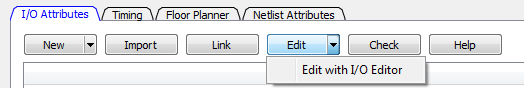
- The I/O Editor opens, as shown in the following figure.
Figure 4-3. I/O Editor 
- Select the XCVR View in the I/O Attribute editor. This view allows you to assign IO locations to XCVR and reference clock.
- Place TX_PLL, XCVR_REF_CLK, and XCVR_Debug, as shown in Figure 4-4 for Evaluation kit.
Figure 4-4. Placing the TX_PLL, XCVR_REF_CLK, and PF_XCVR Components (Evaluation kit) 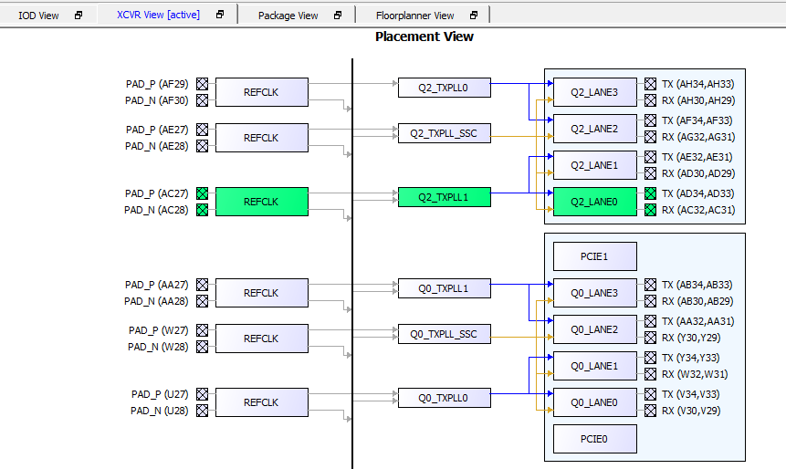
- Select File > Commit to save the placement, then close the I/O Editor (File > Exit).
- Select the Constraint Manager Floor Planner. The constraint file (
fp_constraints_FHB_DIS.pdc or fp_constraints_FHB_EN.pdc) must be visible. Ensure that the file is checked to be used for Place and Route.Figure 4-5. Constraint Files on the Floor Planner Attributes Tab 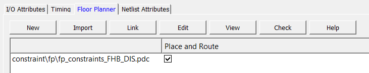
- Double-click Place and Route from the Design Flow tab. When place and route is successful, a green tick mark appears next to Place and Route, as shown in the following figure.
Figure 4-6. Place and Route 