
3 State Machine Design Pattern
Each application task is given its own control loop, consisting of a series of states. Transitions between these states are based on internal or external events, providing a clear, organized structure to handle foreseeable application logic.
A state machine control flow in an embedded application is a programming model where the system’s behavior is divided into a finite number of states. Transitions between these states based on internal or external events provide a clear, organized structure for managing complex and variable interactions.
This approach differs from interrupt and callback-based control flow in that it primarily focuses on the internal state and logic of the application rather than on reacting to external interrupts. State machines offer a predictable, easily maintainable structure for managing different operational modes, while interrupts and callbacks are more about handling asynchronous events and immediate responses to external stimuli.
A state machine-based control flow could be considered an ‘RTOS-ready’ architecture. While MCC Melody does not provide direct RTOS support, if your application has reached the level of required complexity, consider looking at MPLAB Harmony, which has full support for third-party solutions like FreeRTOS™ and Azure® RTOS.
3.1 MCC Melody State Machine - LED Example
The following are code snippets meant to enable easy implementation of the state machine design pattern.
Key reference: Getting Started with PIC16F1xxx MCUs using MCC and State Machines - Microchip University Course.
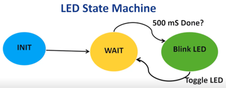
The code snippets below implement the following state machine for an LED. A timer is used to create a 1 ms tick for the application, which increments a timer count in an associated callback function.
A structure is created to hold variables associated with a given task.
Refactoring: As your state machine grows in size, you may want to place this in
app.h.
typedef struct
{
    /* The application's current state */
    APP_LED_STATES state;

    /* TODO: Define any additional data used by the application. */
    uint16_t TimerCount;

} APP_LED_DATA;
The initialization of the LED task sets up the initial values of variables used.
Refactoring: As your state machine grows in size, you may want to place this in
app.c.
void APP_LED_Initialize ( void )
{
    /* Place the App LED state machine in its initial state. */
    app_led_data.state = APP_LED_STATE_INIT;

    /* TODO: Initialize your application's LED state machine and other
     * parameters.
     */
    app_led_data.TimerCount = 0;
}
This is the task state machine associated with the LED.
Refactoring: As your state machine grows in size, you may want to place this in
app.c.
void APP_LED_Tasks ( void )
{
    /* Check the application's current state. */
    switch ( app_led_data.state )
    {
        /* Application's initial state. */
        case APP_LED_STATE_INIT:
        {
            app_led_data.state = APP_LED_STATE_WAIT;
            break;
        }

        /* TODO: implement your application state machine.*/
        case APP_LED_STATE_WAIT:
        {
            if (app_led_data.TimerCount >= 500)  // 500 ms done?
            {
                //yes then blink LED and reset TimerCount
                app_led_data.state = APP_LED_STATE_BLINK_LED;
                app_led_data.TimerCount = 0;
            }
            break;
        }
        case APP_LED_STATE_BLINK_LED:
        {
            LED_Toggle();
            DebugIO_Toggle();
            app_led_data.state = APP_LED_STATE_WAIT; // go back to wait state
            break;
        }

        /* The default state should never be executed. */
        default:
        {
            /* TODO: Handle error in application's state machine. */
            break;
        }
    }
}
Follow the instructions for a 100 ms Timer Use Case for the relevant MCU you are using. AVR, PIC16F18F or dsPIC. Adjust the required time-out to 1 ms.
Here is the application’s main.c. Here, the timer interface sets a
pointer to a specific hardware timer, and a callback function is registered. The
TimerCount variable is incremented in the registered callback
function. In the main while loop, APP_LED_Tasks is run continuously.
Main.c: Here is the easiest implementation of the main file,
assuming the code blocks above are placed in
app.c/app.h.
#include "mcc_generated_files/system/system.h"

const struct TMR_INTERFACE *Timer = &Timer0;
volatile uint16_t Count;

void Timer_Callback_1ms(void){
    app_led_data.TimerCount++;
}

int main(void)
{
    SYSTEM_Initialize();
    APP_LED_Initialize();
    Count = 0;
    Timer->TimeoutCallbackRegister(Timer_Callback_1ms);

    INTERRUPT_GlobalInterruptEnable();

    while(1)
    {
        APP_LED_Tasks();
        APP_KEY_Tasks();
    }
}
Next, a BUTTON is added to the application, which interacts with the LED State Machine in the following way.
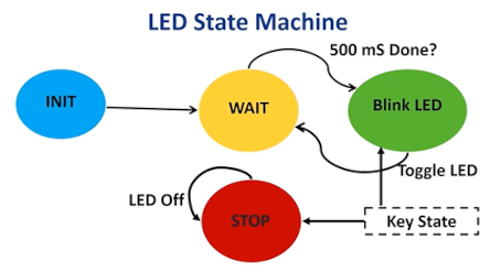
Button_Task checks for a valid keypress on the BUTTON pin. The four
states are INIT, HIGH, LOW and DEBOUNCE.- INIT state - Initializes the start of the task
- HIGH state - The normal default when S2 is not pressed. In it we check for a high-to-low transition. If that occurs, we go to the DEBOUNCE state.
- DEBOUNCE state - Here a 20 ms delay is executed to take care of contact jitter. Once the delay is competed we look for a high-to-low or low-to-high transition.
- LOW state - When the key is
pressed (a low-to-high transition has occurred). Once the keypress occurs, we go
to the DEBOUNCE state.
The blinking LED is stopped if LED blinking is ON or started if LED blinking is OFF.
void APP_KEY_Tasks ( void )
{
    /* Check the application's current state. */
    switch ( app_key_data.state )
    {
        /* Application's initial state. */
        case APP_KEY_STATE_INIT:
        {
            if (BUTTON_GetValue() == 1) // Input high?
                // yes, then go to High state
                app_key_data.state = APP_KEY_STATE_HIGH;
                // no, then go to Low state
            else app_key_data.state = APP_KEY_STATE_LOW;
            break;
        }

        /* TODO: implement your application state machine.*/
        case APP_KEY_STATE_HIGH:
        {
            if (BUTTON_GetValue() == 0) // low transition?
            {
                // yes, then go to Debounce state
                app_key_data.state = APP_KEY_STATE_DEBOUNCE;
                app_key_data.DebounceCount = 0;
            }
            break;
        }
        case APP_KEY_STATE_LOW:
        {
            if (BUTTON_GetValue() == 1)  // high transition?
            {
                // yes, then go to debounce state
                app_key_data.state = APP_KEY_STATE_DEBOUNCE;
                app_key_data.DebounceCount = 0;
            }
            break;
        }
        case APP_KEY_STATE_DEBOUNCE:
        {
            if (app_key_data.DebounceCount >= 20) // 20 ms debounce time over?
                if (BUTTON_GetValue() == 0)         // yes, then check if input low
                    app_key_data.state = APP_KEY_STATE_LOW; // yes, go to low state
                else { // no, then go to high state
                    app_key_data.state = APP_KEY_STATE_HIGH;

                    if (app_led_data.state == APP_LED_STATE_STOP)      // blinking stopped?
                        app_led_data.state = APP_LED_STATE_BLINK_LED;  // yes, then resume blinking
                    else
                        app_led_data.state = APP_LED_STATE_STOP;       // no, then stop blinking
                    }
            // 20 ms debounce time not over, then keep checking in next cycle
            break;
        }

        /* The default state should never be executed. */
        default:
        {
            /* TODO: Handle error in application's state machine. */
            break;
        }
    }
}
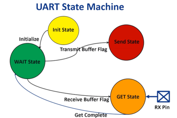
3.2 MCC Melody State Machine - UART Example
- INIT state - The hardware is initialized if needed
- SEND state - If the transmit buffer is empty, the TXREG is loaded with the transmit value
- GET state - The RCREG is read and
the input value is then decoded in the
DecodeSerialroutine - WAIT state - A check for a received char is done. If yes, then the state goes to GET.
Here are the initialization of all three application tasks:
void APP_LED_Initialize ( void )
{
    /* Place the App LED state machine in its initial state. */
    app_led_data.state = APP_LED_STATE_INIT;

    /* TODO: Initialize your application's LED state machine and other
     * parameters.
     */
    app_led_data.TimerCount = 0;
}


void APP_KEY_Initialize ( void )
{
    /* Place the App S2 state machine in its initial state. */
    app_key_data.state = APP_KEY_STATE_INIT;

    /* TODO: Initialize your application's S2 state machine and other
     * parameters.
     */
    app_key_data.DebounceCount = 0;
}


void APP_UART_Initialize ( void )
{
    // Place the App KEY state machine in its initial state.
    app_uart_data.state = APP_UART_STATE_INIT;

    // TODO: Initialize your application's KEY state machine and other
    // parameters.

    app_uart_data.RxChar = 0;
    app_uart_data.TxChar = 0;
}
DecodeSerial is a function which decodes the serial input and
responds appropriately.
- If an ‘A’ is received, then the latest Analog-to-Digital (ADC) value is transmitted
- If an ‘H’ is received, then the “Hello World!” message is transmitted
void DecodeSerial( void )
{

    switch ( app_uart_data.RxChar )
    {
        // 'H' print Hello World!
        case 'H':
        case 'h':
        {
        printf("Hello World! \n\r");
        break;
        }

        default :
            break;
    }
}
void APP_UART_Tasks ( void )
{
    // Check the application's current state.
    switch ( app_uart_data.state )
    {
        // Application's initial state.
        case APP_UART_STATE_INIT:
        {
            app_uart_data.state = APP_UART_STATE_WAIT;
            break;
        }

        // TODO: Implement your application state machine.
        case APP_UART_STATE_SEND:
        {
            if (UART1_IsTxReady()) // TXREG is empty?
            {// yes, then load value to be transmitted in TXREG
                U1TXB = app_uart_data.TxChar;
                app_uart_data.state = APP_UART_STATE_WAIT;
            }
            break;
        }
        case APP_UART_STATE_GET:
        {
            app_uart_data.RxChar = U1RXB; // Read RCREG
            U1RXB = 0;                  // Clear RCREG
            DecodeSerial();             // Decode value received
            app_uart_data.state = APP_UART_STATE_WAIT; // goto WAIT
            break;
        }
        case APP_UART_STATE_WAIT:
        {
            if (UART1_IsRxReady()) // is a char received?
                // yes, then go to GET state
                app_uart_data.state = APP_UART_STATE_GET;
            break;
        }

        // The default state should never be executed.
        default:
        {
            // TODO: Handle error in application's state machine.
            break;
        }
    }
}
3.3 RTOS Design Pattern Introduction
This design pattern is ideal for managing complex, multitasking, and time-sensitive operations. Porting from state machine to RTOS can be smooth due to their complementary nature.
An RTOS-based control flow in embedded applications, ideal for managing complex, multitasking, and time-sensitive operations, facilitates efficient task scheduling and resource management, contrasting with the state machine's linear approach, focusing on internal states and transitions. Key differences include:
1. Task Management - RTOS handles multiple concurrent tasks, while state machines manage a single control flow.
2. Time-Critical Operations - RTOS meets real-time constraints, ensuring predictable execution, unlike state machines.
3. Resource Utilization - RTOS efficiently allocates resources across tasks, unlike state machines centering on logic within states.
4. Complexity and Overhead - Implementing RTOS is an intricate process but offers powerful capabilities for complex applications, whereas state machines are more straightforward.
Porting from a state machine to an RTOS can be smooth due to its complementary nature, as the modularity and defined transitions of state machines align well with the task-based and event-driven model of RTOS, including:
- Modular Design - The distinct states and transitions of the state machines fit the task structure of the RTOS
- Defined State Transitions - Easily managed with RTOS features like message queues and semaphores
- Scalability and Expandability - State machines can expand to multitasking with RTOS
- Event-Driven Nature - Aligns with the RTOS way of handling events through interrupts and callbacks
- Task Prioritization and Timing - Critical in RTOS for timely execution
- Enhanced Resource Management - RTOS optimizes resource use across state machine tasks
However, using RTOS for simple applications can lead to unnecessary complexity and resource overhead.
1. Resource Utilization - RTOSs are built for handling multiple tasks, complex scheduling and resource allocation, potentially leading to unnecessary overhead of memory and CPU usage in a simple application which does not fully utilize these capabilities.
2. Complexity - An RTOS adds layers of complexity in development, requiring a grasp of concepts such as task scheduling, inter-task communication and real-time constraints. This additional complexity may not offer proportional benefits for straightforward applications.
3. Development Time - Setting up an RTOS involves various steps, such as configuring the system, defining tasks and managing their interactions, which can increase the development time compared to simplified control structures.
4. Debugging and Maintenance - Troubleshooting and maintaining an RTOS-based application can be more challenging due to the concurrent nature of tasks and interactions between them. This level of complexity is often unnecessary for simple applications.
A state machine-based control flow could be considered an ‘RTOS-ready’ architecture. While MCC Melody does not provide direct RTOS support, if your application has reached the required level of complexity, consider MPLAB Harmony, which has full support for third-party solutions like FreeRTOS™ and Eclipse ThreadX.