
1 MCC Melody Polling Design Pattern
This sequential form of control flow, waits for each task to be complete, before moving onto the next. Polled or blocking control flow involves continuously checking a for tasks to complete and waiting (blocking) until a specific condition is met.
In an embedded application, a polled or blocking control flow refers to a method of managing hardware interactions where the software continuously checks (or polls) the status of a device and waits (blocks) until a specific condition is met or an operation is completed. During this waiting period, the system does not perform any other tasks, dedicating its resources entirely to monitoring the device’s status.
Key characteristics of this approach are:
-
Simplicity - Polled or blocking control is straightforward to implement, as it involves writing a loop that checks the device status repeatedly until the required condition is satisfied.
-
Deterministic - This method is predictable and deterministic. The program’s flow is easy to understand and trace, as it follows a simple loop until a condition is met.
- Resource Utilization - While waiting for a condition to be met, the CPU is used to continuously poll this condition/flag, so other tasks cannot be performed while waiting. The system is mainly idle when performing other tasks, leading to inefficient use of system resources, especially in systems with limited processing capabilities.
- Power Consumption - A polled implementation is often associated with increased power consumption, due to the inability to put the CPU into a low-power sleep mode while waiting for tasks to finish.
-
Suitability - It is used in simple or time-insensitive applications where multitasking is not required or the overhead of more complex non-blocking approaches is not justified.
However, in applications requiring multitasking or time-critical systems, alternative methods like interrupt-driven or non-blocking I/O are often preferred to avoid the inefficiencies of blocking the system while waiting for hardware operations to complete.
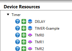
1.1 MCC Melody Support for Polling
Delay Driver
Under Timers, the Delay Driver, provides blocking API.
void DELAY_milliseconds(uint16_t milliseconds) {
    while(milliseconds--){
        __delay_ms(1);
    }
}
ADCx Get Conversion
An ADC conversion will deterministically complete a conversion, once started. So blocking a blocking version of this function is available.
adc_result_t ADCC_GetConversion(adcc_channel_t channel)
{
    adc_result_t res;
    ADC0_StartConversion(channel);
    while(!ADC0_IsConversionDone());
    res = ADC0_GetConversionResult();
    ADC0.INTFLAGS = ADC_RESRDY_bm;
    return res;
}
ADCC_GetSingleConversion (adcc_channel_t
channel).SPI ByteExchange
There are several blocking SPI functions since SPI transfers are deterministic. For example:
void SPI1_BufferExchange(void *bufferData, size_t bufferSize);
void SPI1_BufferRead(void *bufferData, size_t bufferSize);
uint8_t SPI1_ByteExchange(uint8_t byteData);

 uint8_t SPI1_ByteExchange(uint8_t byteData)
{
    SPI1CON2 = SPI1CON2 | _SPI1CON2_SPI1RXR_MASK | _SPI1CON2_SPI1TXR_MASK;
    uint8_t returnValue = 0U;
	SPI1TCNTL = 1;
	//Write input data to SPI transmit buffer register
	SPI1TXB = byteData;
	while(!PIR3bits.SPI1RXIF)
	{
	   //Wait on receive interrupt flag to be set
       };
	//Store received data  from receive buffer register
	returnValue = SPI1RXB;
	return returnValue;
}
1.1.1 Task Routines
Designed to be used with the Polling mode of a Melody Component, the non-blocking task routines check a relevant interrupt flag, even though interrupts are disabled, before calling a callback function.
The Task Routine for the timer means that both Polled and Interrupt/Callback implementations of the following 100 ms Timer example have almost the same code. Unlike the ISR, the only difference is that the callback is called via the Task routine.
- Different tasks could be checked continuously in the main while loop.
- Where available, the Task routine is supported in the interface. The code
below shows the interface mapping, and the specific
TMR1_Tasksimplementation.
#include "mcc_generated_files/system/system.h"
const struct TMR_INTERFACE * Timer = &Timer1;

static void Timer_Callback(void)
{
    IO_LED_Toggle();
    IO_Debug_Toggle();
}
int main(void)
{
    SYSTEM_Initialize();
    Timer->TimeoutCallbackRegister(Timer_Callback);

    while (1)
    {
        Timer->Tasks();
    }
}

const struct TMR_INTERFACE Timer1 = {
    .Initialize = TMR1_Initialize,
    .Start = TMR1_Start,
    .Stop = TMR1_Stop,
    .PeriodCountSet = TMR1_Write,
    .TimeoutCallbackRegister = TMR1_OverflowCallbackRegister,
    .Tasks = TMR1_Tasks
};

void TMR1_Tasks(void)
{
    if(PIR3bits.TMR1IF)
    {
        PIR3bits.TMR1IF = 0;
        TMR1_OverflowCallback();
    }
}
DMA Task Routine
void DMA_Tasks( void )
{
    if(IFS0bits.DMA0IF)
    {
        // DMA Channel0 callback function
        DMA_Channel0_Callback();

        IFS0bits.DMA0IF = 0;
    }
}
1.2 Pin Manager Use Case: LED Toggle on Button Press (Polled)
An LED toggles ON/OFF every time pressing a BUTTON. The program polls a pin to detect the transition associated with a button press.
#include "mcc_generated_files/system/system.h"
#define EDGE_DETECTED        (true)
#define EDGE_NOT_DETECTED    (false)

inline static bool NegEdgeDetectOnButton(void)
{
    static bool lastState = false;

    bool const currentState = BUTTON_GetValue() ? true : false;

    if (currentState != lastState && currentState == false)
    {
        lastState = currentState;
        return EDGE_DETECTED;
    }
    else
    {
        lastState = currentState;
        return EDGE_NOT_DETECTED;
    }
}

static void WaitButton(void)
{
    while (true)
    {
        while (NegEdgeDetectOnButton() == EDGE_NOT_DETECTED) { }
        __delay_ms(50);

        if (BUTTON_GetValue() == 0)
        {
            return;
        }
    }
}

void main(void)
{
    SYSTEM_Initialize();

    while (true)
    {
        WaitButton();
        LED_Toggle();
    }
}
1.3 UART Use Case: Control Commands (Polled)
This example shows how to implement a basic Command Line Interface (CLI), a popular way of sending control commands to the microcontroller over the Universal Asynchronous Receiver and Transmitter (UART). The LED is controlled using commands from a terminal, such as MPLAB Data Visualizer.
LED_SetLow( ) and LED_SetHigh(
), are generated by MCC Melody when configuring a pin and naming it
LED. /* Required header files and define for UART Example 3 */ #include "mcc_generated_files/uart/uart1.h" //Included by: "mcc_generated_files/system/system.h" #include <string.h> #define MAX_COMMAND_LEN 8 void UART_ProcessCommand(void) { if(UART.IsRxReady()) { read_msg = UART.Read(); if(read_msg != '\n' && read_msg != '\r') { command[index++] = read_msg; if((index) > MAX_COMMAND_LEN) { (index) = 0; } } if(read_msg == '\n') { command[index] = '\0'; index = 0; UART_executeCommand(command); } } } void UART_executeCommand(char *command) { if(strcmp(command, "ON") == 0) { LED_SetLow(); printf("OK, LED ON.\r\n"); } else if (strcmp(command, "OFF") == 0) { LED_SetHigh(); printf("OK, LED OFF.\r\n"); } else { printf("Incorrect command.\r\n"); } } int main(void) { SYSTEM_Initialize(); printf("In the terminal, send 'ON' to turn the LED on, and 'OFF' to turn it off.\r\n"); printf("Note: commands 'ON' and 'OFF' are case sensitive.\r\n"); while(1) { UART_ProcessCommand(); } }
1.4 UART Use Case: Control Commands (Polled, Callback Error Handling)
When error handling is enabled, errors are handled using callbacks, an
example of polled code with callbacks, where critical tasks require immediate
attention. In this case, callback functions are registered for various UART errors. In
UART_ProcessCommand( ), the UART.ErrorGet( ) is
called, which then calls the appropriate callback, depending on the error type.
size_t UART1_ErrorGet(void)
{
    uart1RxLastError.status = 0;

    if(U1ERRIRbits.FERIF)
    {
        uart1RxLastError.ferr = 1; //Framing Error
        if(NULL != UART1_FramingErrorHandler)
        {
            UART1_FramingErrorHandler();
        }
    }
    if(U1ERRIRbits.RXFOIF)
    {
        uart1RxLastError.oerr = 1; //Overflow Error
        if(NULL != UART1_OverrunErrorHandler)
        {
            UART1_OverrunErrorHandler();
        }
    }

    return uart1RxLastError.status;
}
The complete code listing is shown below - for the same behavior as the previous UART Control Commands example.
#include "mcc_generated_files/system/system.h"
#include <string.h>

#define MAX_COMMAND_LEN 8
uint8_t command[MAX_COMMAND_LEN];
uint8_t index = 0;
uint8_t read_msg;

void UART_executeCommand(char *command);
void UART_ProcessCommand(void);

void UART_FramingErrorCallback(void);
void UART_OverrunErrorCallback(void);
void UART_ParityErrorCallback(void);

void UART_FramingErrorCallback(void)
{
    (void)printf("UART Framing Error Occurred.\r\n");
}

void UART_OverrunErrorCallback(void)
{
    (void)printf("UART Buffer Overrun Error Occurred.\r\n");
}

void UART_ParityErrorCallback(void)
{
    (void)printf("UART Parity Error Occurred.\r\n");
}

void UART_executeCommand(char *command)
{
    if(strcmp(command, "ON") == 0)
    {
        IO_LED_SetLow();
        (void)printf("OK, LED ON.\r\n");
    }
    else if (strcmp(command, "OFF") == 0)
    {
        IO_LED_SetHigh();
        (void)printf("OK, LED OFF.\r\n");
    }
    else
    {
        (void)printf("Incorrect command.\r\n");
    }
}

void UART_ProcessCommand(void)
{
    if(UART.IsRxReady())
    {
        read_msg = UART.Read();
        size_t error_msg = UART.ErrorGet();
        if ((int)error_msg == 0) // No UART Error after reading
        {
            if (read_msg != '\n' && read_msg != '\r') {
                command[index++] = read_msg;
                if (((int)index) > MAX_COMMAND_LEN) {
                    (index) = 0;
                }
            }
            if (read_msg == '\r') {
                command[index] = '\0';
                index = 0;
                UART_executeCommand(command);
            }
        } else{
           (void)printf("Read error has occurred.\r\n");
        }
    }
}

int main(void)
{
    SYSTEM_Initialize();
    UART.FramingErrorCallbackRegister(&UART_FramingErrorCallback);
    UART.OverrunErrorCallbackRegister(&UART_OverrunErrorCallback);
    UART.ParityErrorCallbackRegister(&UART_ParityErrorCallback);

    (void)printf("In the terminal, send 'ON' to turn the LED on, and 'OFF' to turn it off.\r\n");
    (void)printf("Note: commands 'ON' and 'OFF' are case sensitive.\r\n");

    while(1)
    {
        UART_ProcessCommand();
    }
}