11.2 Printed PCB Antenna Performance of
ATWINC15x0-MR210PB
The printed PCB antenna on the ATWINC15x0-MR210PB is a meandered Inverted F Antenna
(IFA). The antenna is fed via matching network that is matched for the module installed
on a 1.5 mm thick main board (FR4 substrate material). Main board thickness deviation by
±1 mm changes RX/TX performance by ±1 dB maximum, referring to RX/TX performance with a
default antenna-matching network and installed on a 1.5 mm thick main board.
Measured peak antenna gain is -0. 3 dBi.
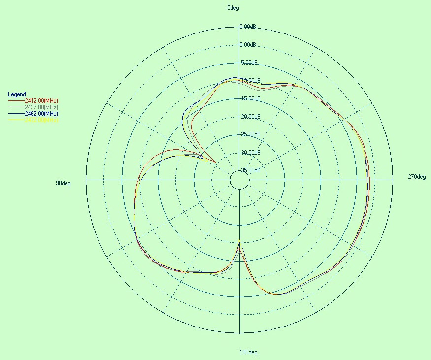
Antenna Radiation Pattern
The following figures illustrate the Antenna Radiation Patterns.Figure 11-3. Antenna Radiation Pattern when
Phi = 0 Degree
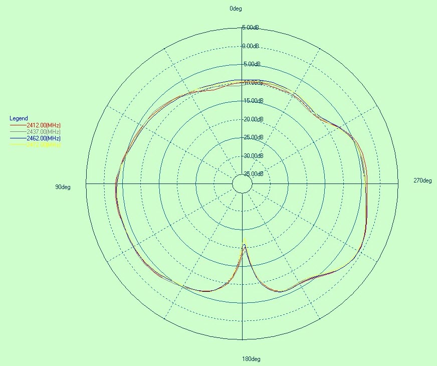
Figure 11-4. Antenna Radiation Pattern when Phi
= 90 Degree
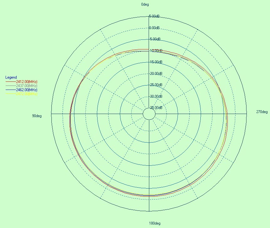
Figure 11-5. Antenna Radiation Pattern when
Theta = 90 Degree
The online versions of the documents are provided as a courtesy. Verify all content and data in the device’s PDF documentation found on the device product page.