2.5 Improved ADC Module
ATiny102/ATiny104 features a 10-bit, successive approximation ADC. The ATtiny102/104 ADC module has more number of ADC channels. The differences are highlighted in the following table.
| Parameter | ATtiny104 | ATtiny102 | ATtiny5/10 |
|---|---|---|---|
| ADC Channels | 8 ADC channels | 5 ADC Channels | 4 ADC Channels |
| PORTs for ADC | ADC pins are available on PORTA and PORTB | ADC pins are available on PORTA and PORTB | ADC pins are available only on PORTB |
While ATtiny5/10 (ATtiny4/9 does not have ADC) features internal reference voltage of VCC, the ATtiny102/104 have internal reference voltage of nominally 1.1V, 2.2V, and 4.3V. Alternatively, VCC can be used as reference voltage for single ended channels.
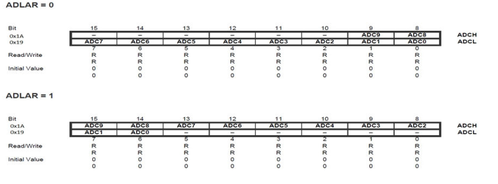
ATtiny102/104 has optional left adjustment for ADC result readout. The ADLAR bit in ADCSRB register affects the presentation of the ADC conversion result in the ADC data register. Write one to ADLAR to left adjust the result. Otherwise, the result is right adjusted. Changing the ADLAR bit affects the ADC Data Register immediately, regardless of any ongoing conversions.

Refer to the Register Description section under the ADC module in the ATtiny102/104 device datasheet for detailed description of registers and refer to section I/O Multiplexing in the ATtiny102/104 device datasheet for details about the pin mapping for this peripheral.
