5.1 Importance of Poles
The function of the error amplifier is to output a signal relating to the deviation between the output voltage and a reference voltage. To use this principle in a switching controller, however, we also need to compensate for phase effects in the output filter. This ensures that the switch reacts in phase with the voltage on the input on the buck converter filter and not the output voltage, Vout. Identifying the poles and zeroes generated by the output filter, as well as the bandwidth, is the first step in designing this compensation network and is given by:
where ω0 is the pole given by the LC output filter. ωZ is given by Cout, where RESR is the equivalent series resistance of the capacitor. The bandwidth, ωc, is given by the switching frequency, fSW.
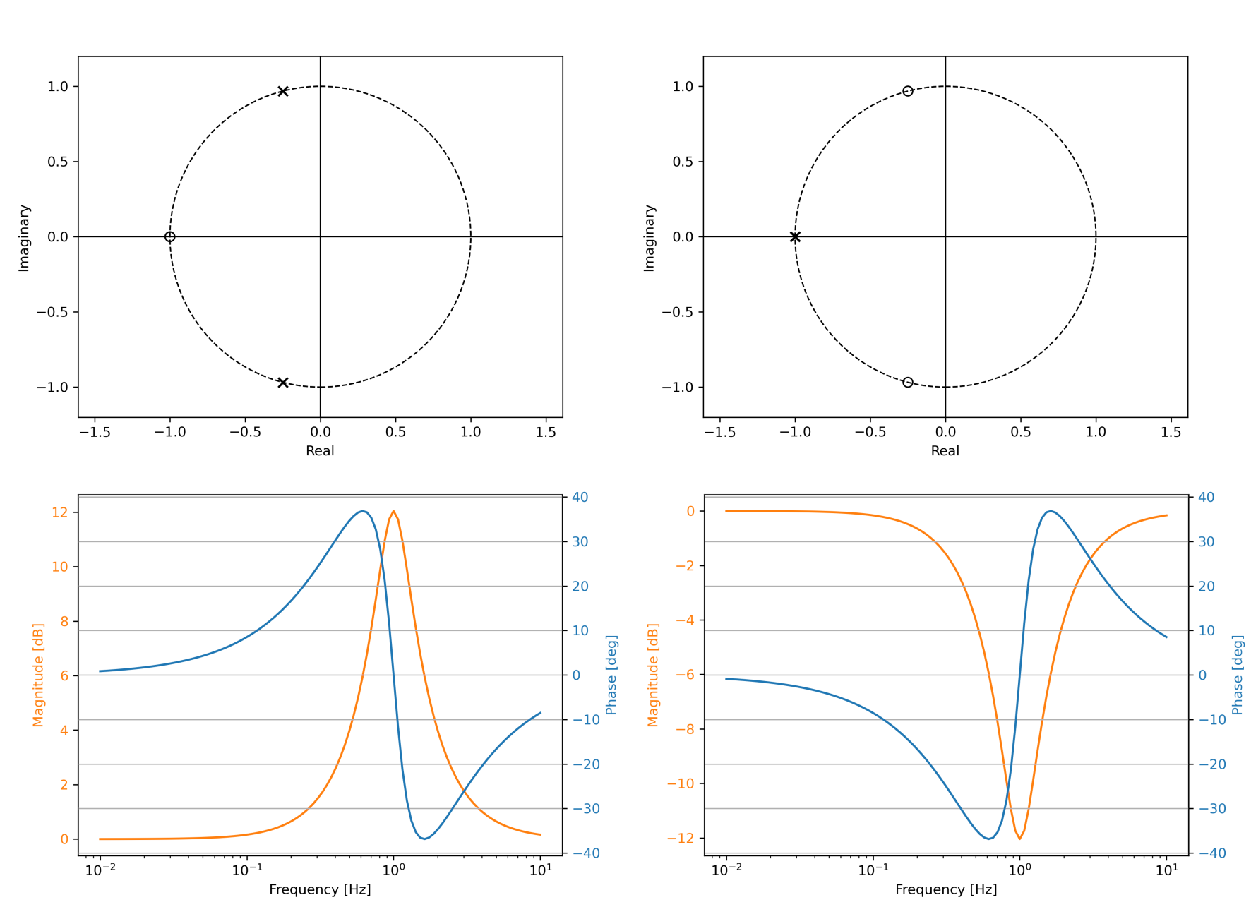
The effects of poles and zeros of the output filter will be canceled out by setting the amplifier zeros equal to output filter poles and amplifier poles equal to output filter zeros. Figure 5-1 shows the poles and zeros as well as the Bode plot of two complementary systems to illustrate the effects of the different parts of this system. The complementary poles and zeros to the output filter of the buck converter are added to the system by the resistors and capacitors in the feedback network, Figure 2-3.