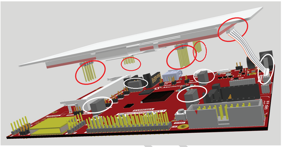
3.2.2 Mechanical Connection of the LCD Module with the Curiosity Board
Once the FFC connecting the board to the module is in place, follow the steps below to position
the AC69T88A correctly on the Curiosity board.
- Position the LCD module so that the four 2x4-pin headers (circled in red) are above the Curiosity board headers (circled in white) as illustrated in Figure 3-4 below.
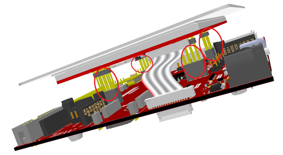
- Be sure that the FFC connecting the two boards is not twisted.
- Push the LCD module headers into the Curiosity board headers as shown in Figure 3-5.
- Make sure that all headers are perfectly aligned and mated in the Curiosity board sockets.