
3.8.3 AWS Cloud IoT Core Application on PIC32CM LS60 Curiosity Pro Evaluation Kit
Description
The PIC32CM LS60 Curiosity Pro evaluation kit is ideal for evaluating and prototyping with the secure and ultra-low power PIC32CM LS60 Arm Cortex-M23 based microcontrollers. The MCU integrates TrustFLEX ECC608 secure subsystem and Arm TrustZone Technology in one package. This specific development board can be pre-provisioned for AWS IoT Core; The application demonstrates MQTT data transfer of light and temperature sensor data from IO1Xpro to AWS IoT core.
Key Highlights of PIC32CM LS60 Curiosity Pro Evaluation Kit
- Additional sensors can be interfaced
using Click boards through an on-board mikroBUS connector.
- Extension headers
- Arduino Uno header connectors
- mikroBUS socket
- Embedded debugger
- USB interface, Host or Device
- Embedded current measurement XAM with Data Visualizer support for real-time power measurement
- One Touch button
- One Potentiometer
- Microcontroller peripheral libraries and Middleware are based on the MPLAB Harmony v3 Software framework
- MPLAB X IDE-based project
- Command Line Interface (CLI) support for Wi-Fi credentials configuration
- 2 User LED's and Push buttons
Components Used
Software/Tools Used
This project has been verified to work with the following versions of software tools:
Refer to the Project Manifest present in
harmony-manifest-success.yml under the project folder
firmware/src/config/pic32cmls_60
- Refer to the Release Notes to know the MPLAB X IDE and MCC Plug-in version
Due to Microchip regularly updates tools, occasionally issue(s) could be discovered while using the newer versions of the tools. If the project does not seem to work and version incompatibility is suspected, it is recommended to double-check and use the same versions that the project was tested with. To download original version of MPLAB Harmony v3 packages, refer to the document How to Use the MPLAB Harmony v3 Project Manifest Feature (DS90003305).
AWS Account Setup
To run the AWS Cloud IoT core solution, an AWS account is required. The following are the steps to configure an AWS account.
Amazon Web Services (AWS) provides computing services for a fee. Some are offered for free on a trial or small-scale basis. By signing up for the AWS account, the user is establishing an account to access a wide range of computing services.
Think of the AWS account as the root account for AWS services. It is very powerful and gives the user complete access. Be sure to protect the username and password. Control access to the AWS account by creating individual users and groups using the Identity and Access Management (IAM) Console. Assign policies (permissions) to the group from the IAM Console.
Create the own AWS account- Create AWS account.
- Go to AWS website and follow instructions to create the own AWS account
- Additional details can be found at create and activate a new AWS account
- Secure root account with MFA
(multi-factor authentication).
- This is an important step to better secure the root account against attackers. Anyone logging in not only needs to know the password. However, a constantly changing code generated by an MFA device.
- AWS recommends a number of MFA device options at the following link Multi-Factor Authentication (MFA) for IAM.
- The quickest solution is a virtual MFA device running on a phone. These apps
provide the ability to scan the QR code AWS will generate to set up the MFA
device.
- Return to Amazon AWS and click the Sign In to the Console.
- If it asks for an IAM user name and password, select the Sign-in using root account credentials link.
- Enter the email and password for the AWS account.
- Under Find Services search for IAM and select it to bring up the Identity and Access Management options.
- Click on Activate MFA (Multi-factor Authentication) on the root account.
- Create an admin IAM user AWS best practices recommend not using the root account for standard administrative tasks, but to create a special admin user for those tasks. See lock-away-credentials
- Follow the instructions at Create an administrative user for creating an admin user.
- Enable MFA (multi-factor authentication) for the admin user. See Require multi-factor authentication (MFA).
The usage of a custom PKI with TrustFLEX devices uses the Just-In-Time Registration (JITR) feature of AWS IoT Core. This feature requires a number of resources setup with an AWS account to work. The creation of these resources is automated through the AWS CloudFormation service.
- Sign into the AWS console using the admin user created in the previous section.
- Change to region to
US East
              (Ohio) (a.k.a. us-east-2)
. This is done from a drop-down in the top right of the console web page after logging in. - Under Find Services search for CloudFormation and select it to bring up that service.
- Click Create Stack button.
- Select Upload a template file from the page of the stack creation.
- Click Choose file and upload the
aws-zero-touch-full-setup.yamlfile.Note: If running from a China region, the user will need to select the aws-zero-touch-full- setup-cn.yaml instead. These files are available in~/.trustplatformfolder. - Click Next to move on to the stack details.
- Enter
TrustFLEXas the stack name. Actual name is not important, just has to be unique. - Enter a password for the user that will be created to run the demo under UserPassword.
- Click Next to move on to the stack options. Nothing needs to be changed here.
- Click Next to move on to the stack review.
- Check the acknowledgment box regarding IAM resources at the bottom of the page.
- Click Create Stack to start the resource creation.
- Wait until the stack creation
completes. This can take a few minutes. Once done, the stack that the user created will
show as
CREATE_COMPLETE. - Save demo credentials. Click the Outputs tab for the stack to see the credentials to be saved.
- Save the credentials to
aws_credentials.yamlfile in~/.trustplatform/aws_credentials.yamlfolder.Note: Indicates windows home directory is /user/username.
AWS Cloud IoT Provisioning Guide
- Install Trust Platform Design Suite version 2 TPDSv2.
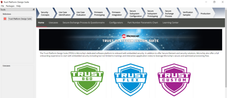
- Launch Trust Platform Design Suite v2
from windows search bar, a window launches as shown below:
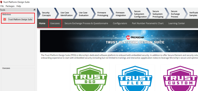
- Select Trust Platform Design Suite in
webviews and click on Usecases.
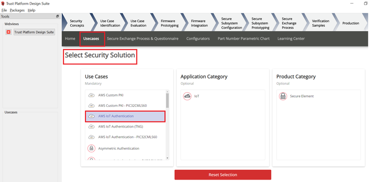
- In Select Security Solution, Under Use
Cases select AWS IoT Authentication.
- Scroll Down and in Available solution
by provisioning flow select AWS IoT Authentication under PIC32CMLS60.

- A Usecase gets launched, click on AWS
IoT Authentication-PIC32CMLS60 from the Usecases.
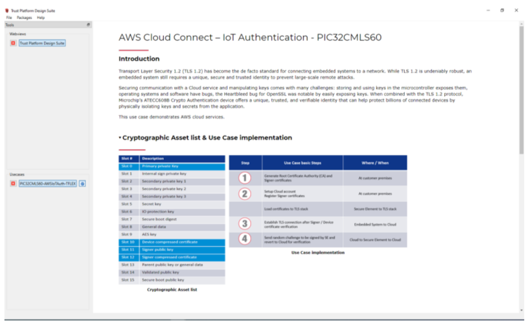
- AWS Cloud Connect – IoT Authentication
page launches as shown below.
- Scroll down and select PIC32CMLS60
Curiosity Pro evaluation kit if not selected.
- Connect both the debug and Target USB to PIC32CMLS60 Curiosity Pro evaluation kit to PC running Trust Platform Design Suite. Connect the WINC1500-Xpro to EXT3 of the kit.
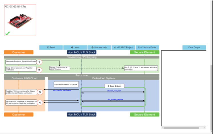
- Scroll down to transaction diagram.
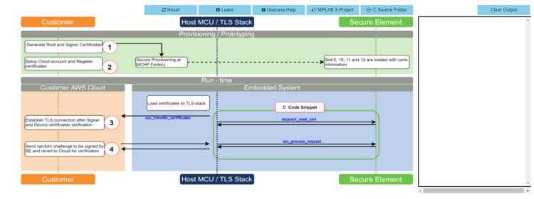
- Click on icon
1and wait till a green right mark appears.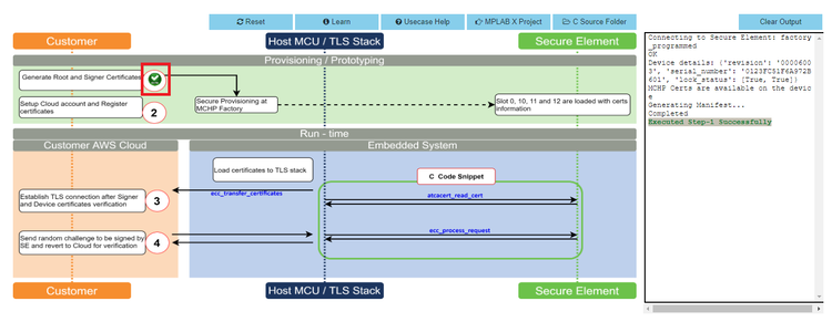
- Sequentially click on icon
2,3and4.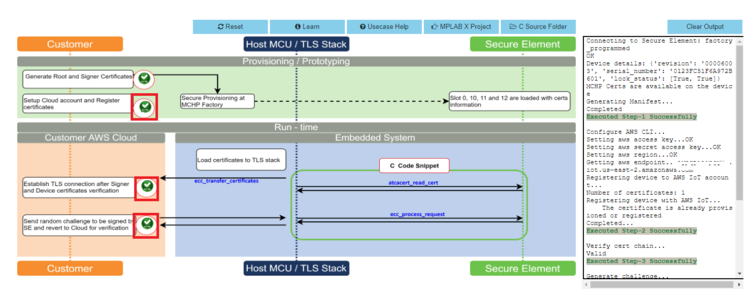
- Note the output in the output window on the right side.
- Once the use case steps are executed
successfully, click on C Source Files and navigate to
.trustplatform\pic32cmls60_cloud_connectand copy theaws_connect.hfile.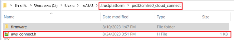
- Replace the
aws_config.hfile in theproject folder(pic32cm_ls60_aws_iot_core)with the file that was copied in the above step.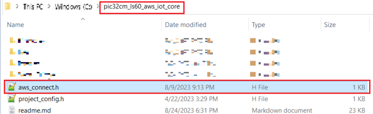
ATWINC1510 Wi-Fi Controller Module Firmware and AWS Root Certificates Upgrade Guide
- Navigate to the Utilities folder inside
the project directory
(pic32cm_ls60_aws_iot_core).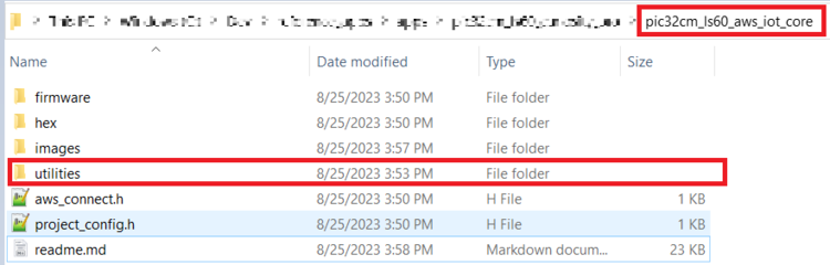
- Follow the steps in readme file inside the utilities folder to do the WINC firmware upgrade.
Application Demonstration
The following sections describes the steps to run the application.
- How to setup the PIC32CMLS60 Development Board
- Connect the Debug USB port of
PIC32CMLS60 Curiosity Pro evaluation kit to the host PC's USB port to power-up the
board.
- The board must be connected through a USB port to perform a firmware upgrade.
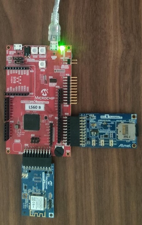
- Connect the WINC1500-Xpro to EXT3 and IO1-Xpro to EXT2 of the PIC32CMLS60 Curiosity Pro evaluation kit.
- Use MPLAB X IDE to Program.
- Configure the Wi-Fi Credentials using Wi-Fi configuration through CLI method explained below.
- Connect the Debug USB port of
PIC32CMLS60 Curiosity Pro evaluation kit to the host PC's USB port to power-up the
board.
- Firmware upgrade and Wi-Fi
configuration process
Firmware upgrade through MPLAB X IDE
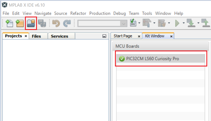
- Connect the kit to the PC. Open
MPLAB X IDE and click on the open project icon as shown below.
- Open the project file from the path
reference_apps_pic32cm/apps/pic32cm_ls60_curiosity_pro/pic32cm_ls60_aws_iot_core/firmware/aws/aws_iot_core_pic32cm_ls60.X - Once the project is opened in the
IDE, click the Make and Program button as shown below and wait till the
Programming completemessage.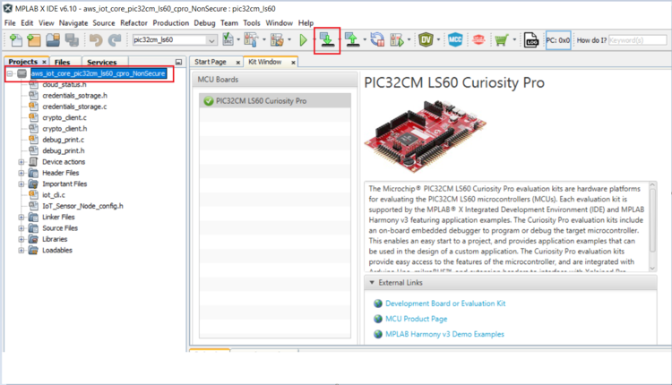 Note:
Note:- Windows OS has a maximum path length of 260 characters and a command-line limitation for Windows OS of 8191 characters. For more details, see Path, File and Folder Name Restrictions section in MPLAB X IDE User´s Guide.
- The TrustZone based project come with long path name. Therefore, the project build may fail due to exceeding Windows maximum path length.
- Workaround: Move the project folder to C:/ drive to reduce the project path length then open in MPLAB X IDE to build the project.
Firmware upgrade through MPLAB X IDE
Most developers usually follow this method to program the .hex file from the MPLAB X IDE environment. Navigate to hex folder inside the project directory
reference_apps_pic32cm/apps/pic32cm_ls60_curiosity_pro/pic32cm_ls60_aws_iot_core/hex/aws_iot_core_pic32cm_ls60.X.production.unified.hexWi-Fi configuration through CLI
- Open a terminal application on the host PC for the virtual COM port of the connected PIC32CMLS60 Curiosity Pro evaluation kit, with 115200-8-None-1 settings.
- Just enter the below command to set
the Wi-Fi credentials.
wifi < SSID >,< PASSWORD >,<
                    SECURITY TYPE >
For example,
wifi MCHP_test,Asdfghjk,2.Note: No need of repeating this step every time while running the demo, device remembers last used Wi-Fi credentials and try to connect to it. If Wi-Fi credentials changes, this step should be performed.
- Connect the kit to the PC. Open
MPLAB X IDE and click on the open project icon as shown below.
- Running the demo application
- After a successful connection, the
PIC32CMLS60 Curiosity Pro evaluation kit pushes the real-time light and temperature
sensors data of the IO1Xpro to the AWS IoT cloud. Toggling of LED0 (Green LED)
indicates the same.
Red LED (LED1) indicates that the Wi-Fi is not connected.
Note: Only Temperature data is pushed by default. Light data is pushed when SW0 is pressed and pressing SW1 stops the publishing of Light sensor data.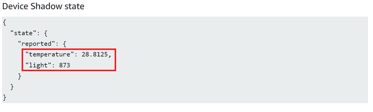 Note: AWS cloud path to visualize the data pushed from the device
AWS IOT>Manage>Things>ThingNAME (ThingNAME =
                    device_serialnumber)>classic Shadow
.
- After a successful connection, the
PIC32CMLS60 Curiosity Pro evaluation kit pushes the real-time light and temperature
sensors data of the IO1Xpro to the AWS IoT cloud. Toggling of LED0 (Green LED)
indicates the same.
The AWS Lambda Service
AWS Lambda is a service that enables code to be run in the cloud without worrying about things, such as provisioning, server management, and scalability. It natively supports many different programming languages, and interfaces with a wide range of other AWS services to facilitate cloud development.
AWS Lambda will be used to transfer temperature and light sensor data from SAM-IoT Development Board to cloud watch. The main concept that the user will focus on is how to route data between AWS Lambda and AWS IoT Core.
- Sensor data is sent from connected devices to the AWS Cloud as MQTT messages.
- The data is forwarded from AWS IoT Core to AWS Lambda, where it is routed to cloud watch for plotting the graph.
- Sign in to the AWS Management Console and select the IAM service.
- Select Roles under Access Management in the menu on the left-hand side.
- Click Create role.
- Select AWS service as the trusted entity.
- Select Lambda as the use case.
- Click Next: Permissions.
- Attach the AWSIoTDataAccess, CloudWatchFullAccess and AWSLambdaBasicExecutionRole permission policies by using the search bar and ticking the relevant boxes. This will allow the Lambda function to send data to the AWS IoT Core and use Amazon CloudWatch logs. Amazon CloudWatch will not be covered in this tutorial. However, it could be a useful tool for debugging the application later on.
- Click Next: Tags.
- Click Next: Review.
- Enter
Lambda_IoT_roleas the Role name. - Click Create role.
AWS Lambda is a service that enables us to run code in the cloud without worrying about server management. It can be set up to send and receive data from many different services, such as AWS IoT Core, which the user will make use of in this tutorial. To create an AWS Lambda function:
- Sign in to the AWS Management Console and select the Lambda service.
- Select Functions in the menu on the left-hand side.
- Click on Create function.
- Choose Author from scratch.
- Enter
iot_Core_to_CwMetricsas the Function name. - Select Python 3.8 as the Run time.
- Expand Choose or create an execution role under Permissions and select Use an existing role.
- Select the
Lambda_IoT_rolethat was defined earlier. - Click on Create function.
When the AWS Lambda function has been successfully created, the user needs to be redirected to the Configuration page for the iot_Core_to_CwMetrics function. This page can be found by selecting Functions in the menu on the left-hand side in AWS Lambda and then selecting the function from the list.
Triggering the Lambda Function for Relevant MQTT PackagesThe next step is to configure the Lambda function to trigger when messages containing sensor data are published over MQTT in AWS IoT Core:
- On the Lambda function's configuration page, expand the Designer panel.
- Click on Add trigger.
- Select AWS IoT as the trigger in the drop-down menu.
- Select Custom IoT rule.
- In the Rule drop-down, select Create new rule.
- Enter
RouteSensorDataas the Rule name. - Enter
SELECT * FROM
              "$aws/things/ThingName/shadow/#"
as the Rule query statement.Note: ThingName is the unique serial number of the device. - Click Add.
- Ensure that the
iot_Core_to_CwMetricsfunction is selected in the Designer panel. - Paste the following Python code in the
editor in the Function code
panel:
import json # Python library for dealing with JSON objects import boto3 # boto3 is the AWS SDK for Python cloudwatch = boto3.client('cloudwatch') #Define payload attributes that may be changed based on device message schema ATTRIBUTES = ['temperature','light','state','reported'] # Define CloudWatch namespace CLOUDWATCH_NAMESPACE = "thingls60/MonitorMetrics" # Define function to publish the metric data to CloudWatch def cw(topic, metricValue, metricName): metric_data = { 'MetricName': metricName, 'Dimensions': [{'Name': 'topic', 'Value': topic}], 'Unit': 'None', 'Value': metricValue, 'StorageResolution': 1 } cloudwatch.put_metric_data(MetricData=[metric_data],Namespace=CLOUDWATCH_NAMESPACE) return # Define the handler to loop through all the messages and looks to see if the message attributes # include light or temp and calls the cw() function if so to publish the custom metrics to Amazon CloudWatch def lambda_handler(event, context): my = list(event.values()) my_list = list(my[0].values()) print(my_list[0]) for e in my_list[0]: print("Received a message: {}".format(str(e))) print(e) # Potential test point # Iterate through each attribute we'd like to publish for attribute in ATTRIBUTES: # Validate the event payload contains the desired attribute if attribute in e: print("publishing {} to CloudWatch".format(attribute)) cw("PIC32CMLS", my_list[0][attribute], attribute) return event - Click Save.
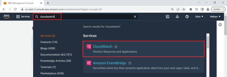
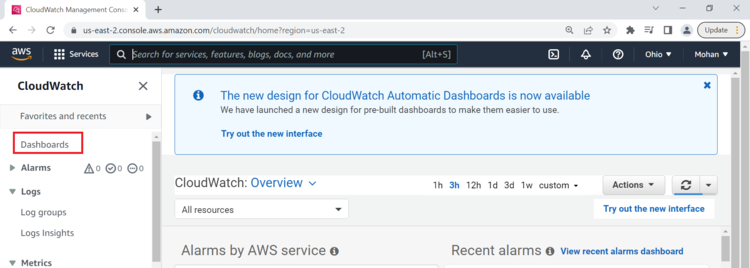
- Search CloudWatch in AWS search box and
open it.
- Click on Dashboard on the right
side of the window under CloudWatch.
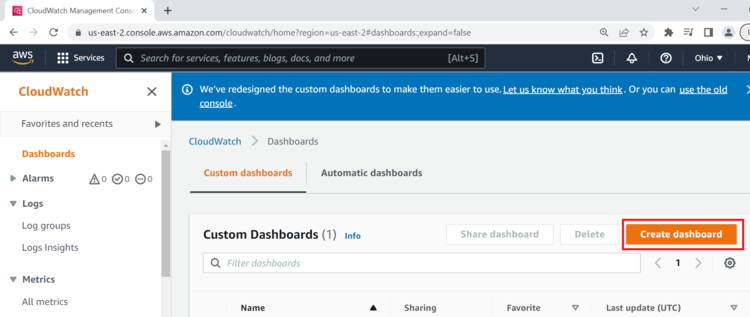
- Click on Create Dashboard.
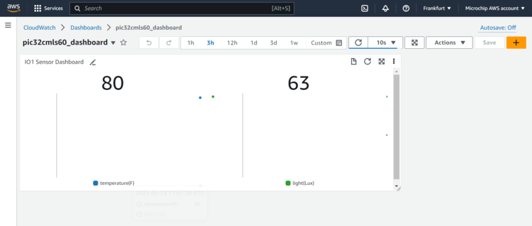
- Enter Dashboard name as
pic32cmls60_dashboardand click on Create Dashboard.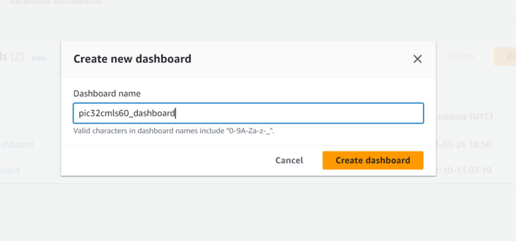
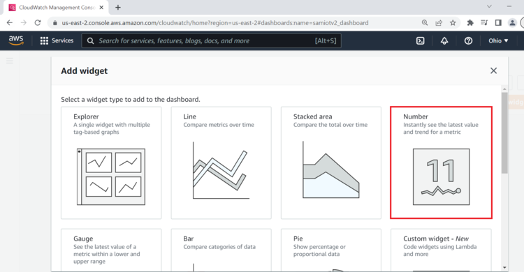
- Under Add widget Select Number.
- Under Add metric graph, select
thingls60/MonitorMetricsand thentopic.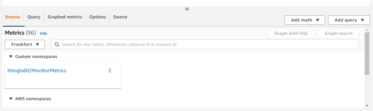
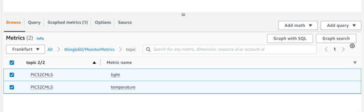
- Under Metrics, select both
PIC32CMLStemperature and light metrics.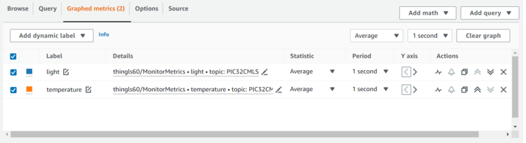
- Navigate to Graphed metrics and change
the period to 1 second in both temperature and light metrics. Then, click on Create
widget.
- Click Save dashboard.
This Dashboard page refreshes every 10 seconds and update the sensor data.
Note: The custom dashboard can be found inCloudWatch>Dashboards>the dash board name(here it ispic32cmls60_dashboard).Thenon-secure temperaturedata is shown by default. To viewsecure light sensordata press SW0 on the PIC32CMLS60 Curiosity Pro evaluation kit. To stop viewing it press SW1.
Reference
- For more details on the application usage, functionality and other details, refer to the PIC32CM LS60 Curiosity Pro Evaluation Kit User Guide (DS70005443)
Comments
- This application demo builds and
works out of box by following the instructions in Running the Demo section. If the
user needs to enhance/customize this application demo, should use the MPLAB Harmony v3
Software framework. Refer to the following links below to setup and build the
applications using MPLAB Harmony.
- How to Setup MPLAB Harmony v3 Software Development Framework (DS90003232)
- How to Build an Application by Adding a New PLIB, Driver, or Middleware to an Existing MPLAB Harmony v3 Project (DS90003253)
- Video - How to Set up the Tools Required to Get Started with MPLAB® Harmony v3 and MCC
- Create a new MPLAB Harmony v3 project using MCC
- Update and Configure an Existing MHC-based MPLAB Harmony v3 Project to MCC-based Project