
22 (PWM) Pulse-Width Modulation
The PWM module generates a Pulse-Width Modulated signal determined by the duty cycle, period, and resolution that are configured by the following registers:
- TxPR
- TxCON
- PWMxDC
- PWMxCON
Important: The corresponding TRIS bit must be cleared to
enable the PWM output on the PWMx pin.
Each PWM module can select the timer source that controls the module. Each module has an independent timer selection which can be accessed using the CCPTMRS1 register. Note that the PWM mode operation is described with respect to TMR2 in the following sections.
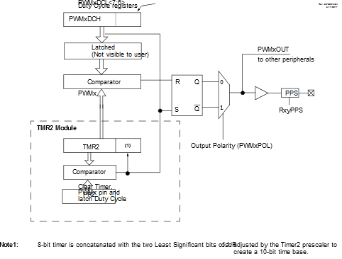
Figure 22-1 shows a simplified block diagram of PWM operation.
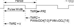
Figure 22-2 shows a typical waveform of the PWM signal.
For a step-by-step procedure on how to set up this module for PWM operation, refer to 22.9 Setup for PWM Operation Using PWMx Output Pins.